
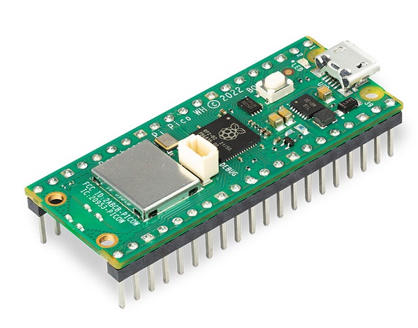
The Raspberry Pi Pico WH is just like the classic Pico but adds pre-soldered headers, a new 3-pin debug connector, and an on-board single-band 2.4GHz wireless interfaces (802.11n) using the Infineon CYW4343 while retaining the Pico form factor.
The on-board 2.4GHz wireless interface has the following features:
- Wireless (802.11n), Single-band (2.4 GHz) WiFi with WPA3 and Soft Access Point supporting up to 4 clients
- Bluetooth Low Energy - note this isn't supported in software yet, its just a hardware capability.
- The wireless interface is connected via SPI to the RP2040 microcontroller and has a micropython driver for wireless capability
Due to pin limitations (the Pico brings out all the GPIO) some of the wireless interface pins are shared with the exposed pads:
- The SPI CLK is shared with VSYS monitor, so only when there isn’t an SPI transaction in progress can VSYS be read via the ADC.
- The Infineon CYW43439 SPI DIN/DOUT and IRQ all share one pin on the RP2040. Only when an SPI transaction isn’t in progress is it suitable to check for IRQs.
- The interface typically runs at 33MHz.
For best wireless performance, the antenna should be in free space. For instance, putting metal under or close by the antenna can reduce its performance both in terms of gain and bandwidth. Adding grounded metal to the sides of the antenna can improve the antenna’s bandwidth.
The Pico WH comes with soldered headers for use in a breadboard or perfboard or can be soldered directly onto a PCB. There's 20 pads on each side, with groups of general purpose input-and-output (GPIO) pins interleaved with plenty of ground pins. All of the GPIO pins are 3.3V logic, and are not 5V-safe so stick to 3V! You get a total of 25 GPIO pins, 3 of those can be analog inputs (the chip has 4 ADC but one is not broken out). There are no true analog output (DAC) pins.
On the slim green board is minimal circuitry to get you going: A 5V to 3.3V power supply converter, green LED connected through on the wireless module, boot select button, RP2040 chip with dual-core Cortex M0, Wireless chipset with antenna, 2 MegaBytes of QSPI flash storage, and crystal.
Inside the RP2040 is a 'permanent ROM' USB UF2 bootloader. What that means is when you want to program new firmware, you can hold down the BOOTSEL button while plugging it into USB (or pulling down the RUN/Reset pin to ground) and it will appear as a USB disk drive you can drag the firmware onto.
For peripherals, there are two I2C controllers, two SPI controllers, and two UARTs that are multiplexed across the GPIO - check the pinout for what pins can be set to which. There are 16 PWM channels, each pin has a channel it can be set to (ditto on the pinout).
You'll note there's no I2S peripheral, or SDIO, or camera. Instead of having specific hardware support for serial-data-like peripherals like these, the RP2040 comes with the PIO state machine system which is a unique and powerful way to create custom hardware logic and data processing blocks that run on their own without taking up a CPU.
RP2040 Chip features:
- Dual ARM Cortex-M0+ @ 133MHz
- 264kB on-chip SRAM in six independent banks
- Support for up to 16MB of off-chip Flash memory via dedicated QSPI bus
- DMA controller
- Fully-connected AHB crossbar
- Interpolator and integer divider peripherals
- On-chip programmable LDO to generate core voltage
- 2 on-chip PLLs to generate USB and core clocks
- 30 GPIO pins, 4 of which can be used as analog inputs
- Peripherals
- 2 UARTs
- 2 SPI controllers
- 2 I2C controllers
- 16 PWM channels
- USB 1.1 controller and PHY, with host and device support
- 8 PIO state machines


