
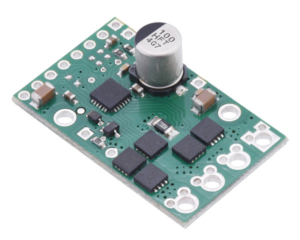
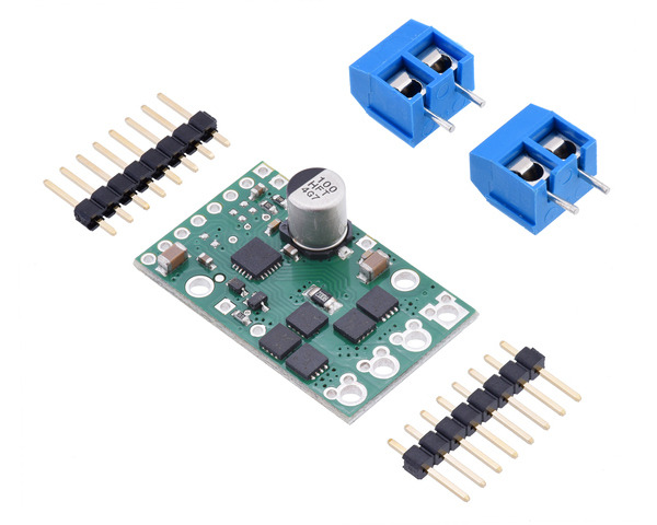
2992-POLOLU, Pololu G2 High-Power Motor Driver 24v13
This discrete MOSFET H-bridge motor driver enables bidirectional control of one high-power DC brushed motor. The small 1.3″ × 0.8″ board supports a wide 6.5 V to 40 V voltage range and is efficient enough to deliver a continuous 13 A without a heat sink. Additional features of this second-generation (G2) driver include reverse-voltage protection along with basic current sensing and current limiting functionality.
Note: Battery voltages can be much higher than nominal voltages when they are charged, so the maximum nominal battery voltage we recommend is 28 V unless appropriate measures are taken to limit the peak voltage.
Features:
- Operating voltage: 6.5 V to 40 V (absolute maximum)
- Output current: 13 A continuous
- Inputs compatible with 1.8 V, 3.3 V, and 5 V logic
- PWM operation up to 100 kHz
- Current sense output proportional to motor current (approx. 40 mV/A; only active while H-bridge is driving)
- Active current limiting (chopping) with default threshold of 30 A (can be adjusted lower)
- Reverse-voltage protection
- Undervoltage shutdown
- Short circuit protection
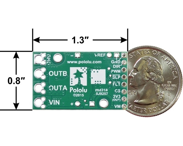
Dimensions:
| Size: | 1.3″ × 0.8″ |
|---|---|
| Weight: | 3.3 g1 |
General specifications:
| Motor channels: | 1 |
|---|---|
| Minimum operating voltage: | 6.5 V |
| Maximum operating voltage: | 40 V2 |
| Continuous output current per channel: | 13 A3 |
| Current sense: | 0.04 V/A |
| Maximum PWM frequency: | 100 kHz |
| Minimum logic voltage: | 1.8 V |
| Maximum logic voltage: | 5.5 V |
| Reverse voltage protection: | Yes |
Notes:
- 1
- Without included connectors.
- 2
- Absolute maximum; higher voltages can permanently destroy the motor driver. Recommended maximum is approximately 34 V, which leaves a safety margin for ripple voltage on the supply line.
- 3
- Typical results with 100% duty cycle at room temperature.
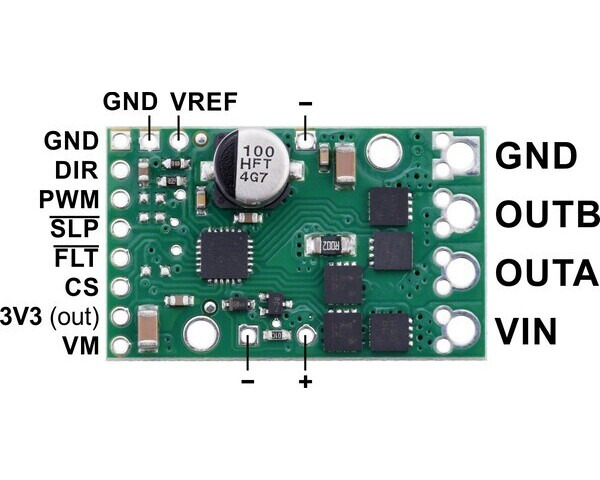
Pinout:

| PIN | Default State | Description |
|---|---|---|
| VIN | Main 6.5 V to 40 V (absolute max) motor power supply connection. | |
| VM | Motor power after reverse-voltage protection. For low-current outputs only. | |
| +, − | Pads for a power supply capacitor (connected to VM and GND). | |
| 3V3 (out) | Regulated 3.3 V output. Provides a few milliamps. Disabled in sleep mode. Warning: Do not short this to VM pin! | |
| GND | Ground connection for logic and motor power supplies. | |
| OUTA | Motor output A (to one motor terminal). | |
| OUTB | Motor output B (to other motor terminal). | |
| PWM | LOW | PWM input controls motor speed. |
| DIR | LOW | Direction input (OUTA to OUTB if high, OUTB to OUTA if low). |
| SLP | HIGH | Sleep input (active low). Board "md31c" pulls high by default. |
| FLT | Fault indicator (active low, open-drain output). | |
| CS | Current sense output (~40 mV/A + 50 mV offset). | |
| VREF | Reference input to adjust current limit threshold. |
| Motor Driver Truth Table | ||||
|---|---|---|---|---|
| PWM | DIR | OUTA | OUTB | Operation |
| H | H | H | L | Forward |
| H | L | L | H | Reverse |
| L | X | L | L | Brake |

Warning: This motor driver has no over-temperature shut-off. An over-temperature or over-current condition can cause permanent damage to the motor driver.


