
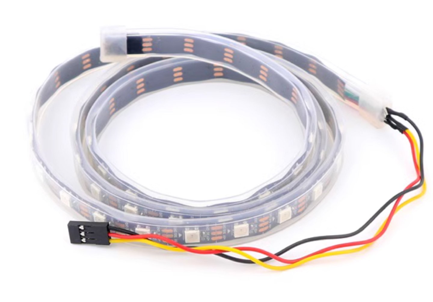
1 Meter Programmable 5050 RGB LED Strip with 60 addressable LEDs and 3-pin Dupont connector. Perfect for Arduino, ESP32, or Raspberry Pi projects with smooth color transitions and custom lighting effects.
Features:
- Length: 1 meter
- LED Type: 5050 RGB, individually addressable
- LED Density: 60 LEDs per meter
- Input Voltage: 5V DC
- Interface: 3-pin Dupont (GND, Data, VCC)
- Water-resistant coating
- Flexible PCB, cuttable between LEDs
- Compatible with WS2812 / similar control protocols
How to get started:
What you will need:
- LED Strip
- Parts we recommend:
- A power supply, (5V, 2A) - 276-ADA
- Jumper wires - JW-75
- Microcontroller Board (Arduino Uno) - ARBAUNO
Last but not least, an access to a computer that can run Arduino IDE.
Firstly, using the code below:
#include <FastLED.h>
#define DATA_PIN 6
#define NUM_LEDS 60 // Example number of LEDs
CRGB leds[NUM_LEDS];
void setup() {
FastLED.addLeds<WS2812B, DATA_PIN, GRB>(leds, NUM_LEDS); // or NEOPIXEL, or your specific LED type
}
void loop() {
// Example: Red
fill_solid(leds, NUM_LEDS, CRGB::Red);
FastLED.show();
delay(500);
// Example: Green
fill_solid(leds, NUM_LEDS, CRGB::Green);
FastLED.show();
delay(500);
// Example: Blue
fill_solid(leds, NUM_LEDS, CRGB::Blue);
FastLED.show();
delay(500);
// Example: Rainbow
fill_rainbow(leds, NUM_LEDS, 0, 7);
FastLED.show();
delay(30);
}
Copy and paste it to Arduino IDE. Next please connect from the dupont wire of the LED Strip using the jumper wires to the Arduino UNO. Please note that Red wire is +5V, Yellow wire is signal and Black wire negative. As per the code line, #define DATA_pin 6, this indicates that the yellow wire from the dupont should be connected using a jumper wire to pin #6. Pin #6 is on the right side of Arduino Uno board. The Red and black will be connected from the dupont to positive 5V and GND of the left side of Arduino UNO board. Once all this is complete, you can go ahead and connect the USB cable and then upload the code into the board. It will light up the following colours: Red, Green and Blue in different phases as per the code above. Once thats complete, disconnect the USB cable and then connect the 5V power supply into the ArduinoUNO board. The 2 images below illustrates the wiring. The first one between the dupont 3 pin wire and the Arduino UNO. The second being the complete wiring setup.
Dupont 3 pin wire to the Arduino UNO Labelled

Complete wiring setup Labelled


