

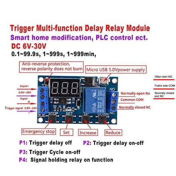
This is a 6~30V timing control delay relay trigger cycle switch module with Micro-USB connection.
Features:
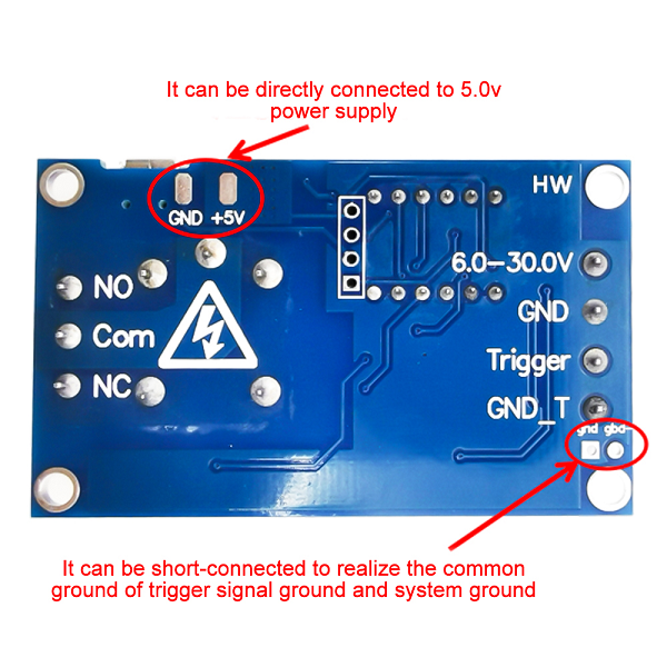
Wide voltage power supply (6~30V) supports micro-USB 5.0V power supply or TYPE-C interface power supply. Two interfaces can be selected.
With one button emergency stop function (STOP key), with reverse connection protection, reverse connection does not burn.
You can set different OP, CL, and LOP parameters, which are independent of each other and saved separately.
All set parameters are automatically saved after power down.
Type 1 Specifications:
1: Working voltage: 6-30V, supporting micro-USB data 5.0V power supply
2: Trigger source: High level (3.0V-24V), with optocoupler isolation, which can improve the anti-interference ability of the system (customers can also short common points).
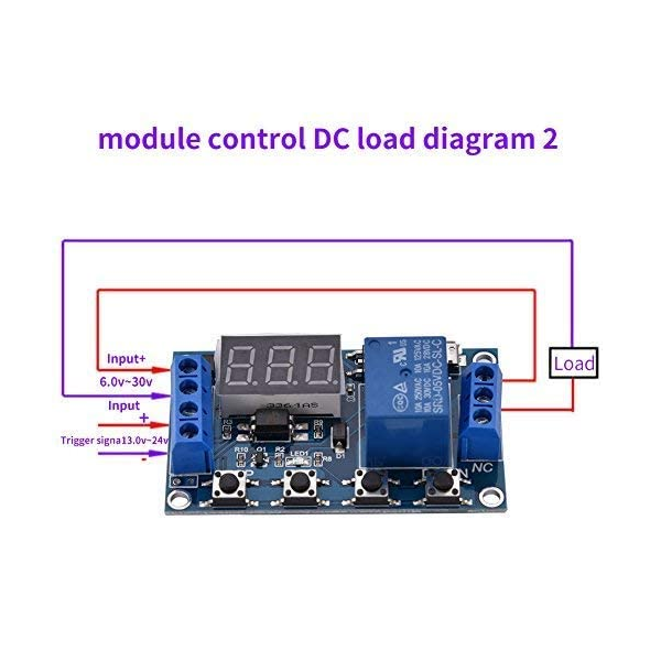
3: Output function: It can control DC 30VDC 5A or 5A 220VAC equipment.
4: Static current: 20 mA; Working current: 50mA
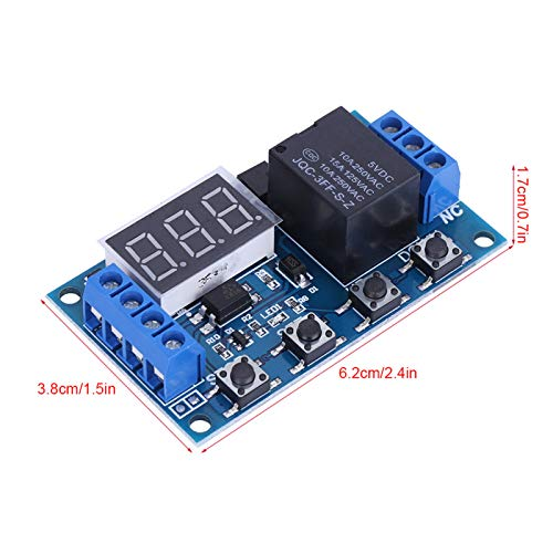
- Service life: over 100000 times; Working temperature: - 40-85 ℃; Dimensions:
6: Optocoupler isolation, enhanced anti-interference ability, industrial grade motherboard.
Special note: The relay output is a passive contact, just a switch.
TYPE-C interface:
Working voltage: 6-30V
Support: TYPE-C 5.0V power supply
Trigger signal source: High level trigger (3.0V-24V) signal ground and system ground are not in common to improve the anti-interference ability of the system (it can also be shorted to common ground by itself).
Output capacity: It can control equipment within 30V5A DC or 220VAC 5A.
Static current: 20mA Working current: 50mA.
Service life: more than 100000 times
Working temperature: - 40-85 ℃
With optocoupler isolation, enhanced anti-interference ability, industrial grade circuit board, set parameters for permanent power failure.
Memory.
Operating mode:
P1: After the signal is triggered, the relay turns on for OP time and then turns off; During the OP time, proceed as follows:
P1.1: Signal triggered again invalid
P1.2: The signal triggers a retiming again
P1.3: The signal triggers reset again, the relay is disconnected, and the timing stops;
P-2: Gives a trigger signal, and after the relay turns off CL time, the relay turns on OP time. After the timing is completed, turns off the relay.
P3.1: After the trigger signal is given and the relay is turned on for an OP time, the relay is turned off for a CL time, and then the above actions are cycled. If the signal is given again within the cycle, the relay is turned off and the timer is stopped; The number of cycles (LOP) can be set;
P3.2: After powering on, there is no need to trigger a signal, the relay turns on OP time, and the relay turns off CL time. Cycle the above actions; The number of cycles (LOP) can be set;
P-4: If there is a trigger signal for the signal holding function, the timer will be cleared and the relay will remain on; When the signal disappears, turn off the relay after timing OP; During the timing period, if there is another signal, the timing will be cleared;
Note:
- Pay attention to the wiring as shown in the figure, and do not connect it incorrectly.
2. This document only represents the product parameters at the time of editing, and is subject to change without notice.
3. The relay output is a passive contact, which is not energized and controls the on-off of a line.
Timing range: 0.1 seconds (minimum) to 999 minutes (maximum) continuously adjustable
How to select a timing range:
After setting the parameter values in the mode selection interface, press the STOP key briefly to select the timing range;
30. The decimal point is in one place, and the timing range is from 1 second to 999 seconds
20. X decimal point in ten places, timing range: 0.1 seconds to 99.9 seconds
X.X.X. The decimal point is fully lit, and the timing range is 1 minute to 999 minutes
For example, if you want to set the OP to 3.2 seconds, move the decimal point to ten places, and the nixie tube displays 03.2
Parameter description: OP ON time, CL OFF time, LOP cycle times (1-999 times, "---" represents infinite cycles)
These parameters are independent of each other, but each mode shares these parameters. For example, if the ON time OP is set to 5 seconds in P1.1, and the user wants to switch to P1.2 mode, when entering P1.2 to set the corresponding parameters, the OP will also be 5 seconds;
Briefly press the SET key on the main interface (display 000) to display OP (CL, LOP) and the corresponding time XXX;
If there is only OP time in the mode (such as mode P1.1, P1.2, P1.3), briefly pressing the SET key will display only OP and the corresponding time;
If there are OP, CL, and LOP in the mode (such as P3.1, P3.2), briefly pressing the SET key will display OP and corresponding time, CL and corresponding time, LOP, and corresponding times;
After setting the mode, you can easily view the parameters set in the current mode by briefly pressing the SET key on the main interface.
How to set parameters:
1.Determine the working mode of the relay.
2.According to the working mode of the relay, in the main interface (when the module is powered on, it will flash down the current working mode (default P1.1 mode), and then enter the main interface.) "Press and hold the SET key for 2 seconds and then release" to enter the mode selection interface. Press and hold the UP and DOWN keys briefly to select the mode to be set (P1.1~P-4);
3.After selecting the mode to be set (such as P3.2), briefly press the SET key to set the corresponding parameters. At this time, the parameters to be set will flash (OP ON time, CL OFF time, number of LOP cycles ("---" represents infinite cycles). Adjust the parameter value through UP and DOWN, and support long press (fast increase or decrease) and short press (increase or decrease by 1 unit); After setting the parameter value, press the STOP key briefly to select the decimal point position and timing range (corresponding time 0.1 seconds to 999 minutes); Briefly press the SET key to set the next parameter of the current mode. The process is the same as above.
- After setting the parameters for the selected mode, press and hold the SET key for 2 seconds, and then release it. The currently set mode will flash, and then return to the main interface. Setting the parameters is successful.
Main interface: "000" (without decimal point) is displayed when the relay is not working, and there is a decimal point when the relay is working.
Mode selection interface: Press and hold the SET key to enter. After setting, press and hold the SET key to exit and return to the main interface.
Relay usage mode:
- ON: The relay is allowed to conduct during the OP conduction time.
- OFF: The relay is prohibited from conducting and always in the OFF state.
Briefly press the STOP button on the main interface to switch between ON and OFF. The current state will flash, and then return to the main interface. (This function is an emergency stop function, which opens and closes the relay with one button)


