
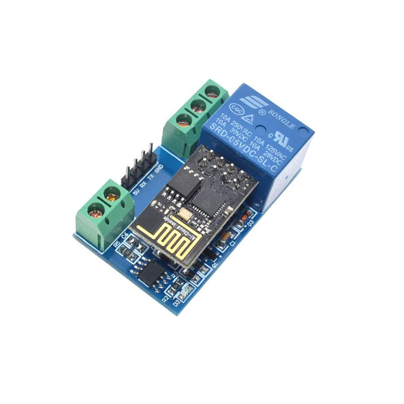
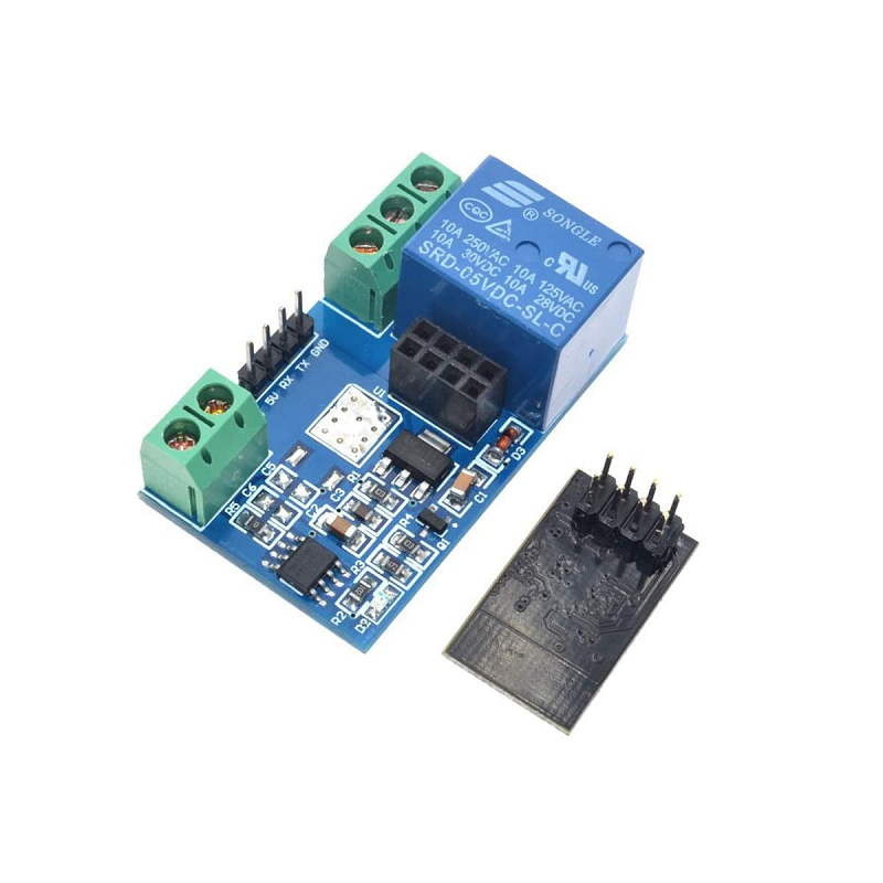
ESP8266 Wireless Single Channel Relay Breakout Board, 5VDC
This is a neatly designed board that offers the ability to control a relay using an ESP8266.
1) You need a 3.3V USB to Serial converter (FTDI FT232 or similar) connect to this module. The FTDI TX pin goes to the RX pin of the module and the FTDI RX pin goes to TX pins of the module. Finally, connect FTDI GND to the module GND. You also need an external 5VDC to power up the board. The purpose of this connection is to start a ESP8266 server at TCP port 8080.
Enter the following AT commands to activate the server (You can use the Arduino IDE serial monitor as a terminal, the baud rate was set to 9600)
AT+CIPMUX=1
AT+CIPSERVER=1,8080
2) You also need an Android app to control the relay. For me I use an app called "Wifi Controller" but I think other app should work as well.
3) Open your phone wireless setting, you should see an SSID named "AI-THINKER_XXXXX". You can go ahead and connect to it. By default, the ESP8266 IPv4 address is 192.168.4.1. Once you are connected to the ESP8266, you can send the following HEX values to control the relay.
send A0 01 01 A1 will turn off the relay
send A0 01 00 A2 will turn on the relay
Note that you will need to redo step 1 if the relay module loses power.
For more information follow this link. (English only)
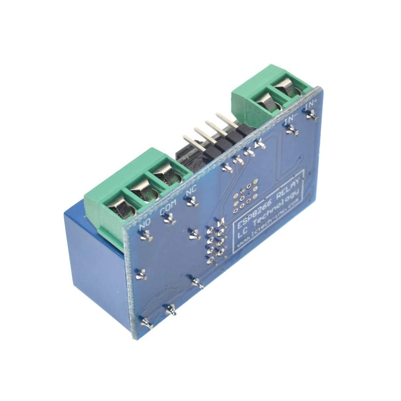
Specifications:
- Operating Voltage: 5VDC
- Max Current: 10Amps @ 30VDC
- Dimensions: 45 x 28 x 16mm


