GK-SERVO-9G geeekus 180 Degrees Analog Servo Motor 9G
The geeekus 180 degree 9G servo motor comes with a set of 4 horns (unlike similar SG90 servos which come with 3) and is excellent for students, hobbyists or educators who want to make stuff move.
The servo has three interfaces,distinguished by brown, red and orange line (sometimes colors differ). Brown line is for GND, red one for power 5V, orange one for signal terminal (PWM signal). The rotation angle of servo is controlled by regulating the duty cycle of the PWM(Pulse-Width Modulation) signal. The standard cycle of the PWM signal is fixed at 20ms (50 Hz), and the pulse width is distributed between 1ms-2ms. The pulse width corresponds to the rotation angle ( 0°~180°) of servo.

Parameters
- Operating voltage: DC 4.8V〜6V
- Angle range: about 180°
- No-load speed: 0.12±0.01 sec/60(DC 4.8V); 0.1±0.01 sec/60(DC 6V)
- No-load current: 200±20mA(DC 4.8V); 220±20mA(DC 6V)
- Stop torque: 1.1±0.01kg/cm(DC 4.8V); 1.3±0.1kg/cm(DC 6V)
- Stop current: 600±30mA(DC 4.8V); 750±30mA(DC 6V)
- Standby current: 4±1mA(DC 4.8V); 4±1mA(DC 6V)
- Operation temperature: -10℃〜50℃
- Save temperature: -20℃〜60℃
- Motor wire length: 250 ± 5 mm
- Dimensions: 22.7mm*12.12mm*25.7mm
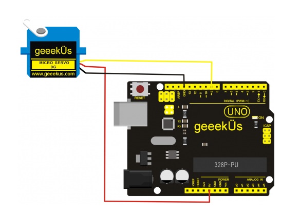
Connection Diagram
Connect the motor to digital pin 9

Sample Program
There are two ways to control a servomotor with Arduino. One is to use a common digital sensor port of Arduino to produce square wave with different duty cycle to simulate PWM signal and use that signal to control the positioning of the motor. Another way is to directly use the Servo function of the Arduino to control the motor. In this way, the program will be easier but it can only control two-contact motor for the servo function, only digital pin 9 and 10 can be used. The Arduino drive capacity is limited. So if you need to control more than one motor, you will need external power.
Method 1:
Sample program A
Method 2:
Let's first take a look at the Arduino built-in servo function and some common statements.
- 1. attach(interface)——select pin for servo, can only use pin 9 or 10.
- 2. write(angle)——used to control the rotate angle of the servo, can set the angle among 0 degree to 180 degree.
- 3. read()——used to read the angle of the servo, consider it a function to read the value in the write() function.
- 4. attached()——determine whether the parameter of the servo is sent to the servo pin.
- 5. detach()—— disconnect the servo and the pin, and the pin(digital pin 9 or 10) can be used for PWM port.
Note: the written form of the above statements are " servo variable name. specific statement ()", e.g. myservo. Attach (9).
Still, connect the servo to pin 9.
Sample program B
#include <Servo.h>
/*define a header file. Special attention here, you can call the servo function directly from Arduino's software menu bar Sketch>Importlibrary>Servo, or input  #include <Servo.h>. Make sure there is a space between #include and  <Servo.h>. Otherwise, it will cause compile error. */
Servo myservo;// define servo variable name
void setup()
{
myservo.attach(9);// select servo pin(9 or 10)
}
void loop()
{
myservo.write(180);// set rotate angle of the motor
}


