
Stepper motors are used for CNC machines, 3D printers, and whenever else one needs precise, powerful motion. But to get good behavior from steppers, you need a motor driver chip that can provide high bursts of current, and for smooth motion, be able to PWM that current for microstepping support.
You can DIY this with a lot of timers, a microcontroller, and an H-Bridge chip - or you could take the easy way out and use an Adafruit STSPIN220 Stepper Motor Driver Breakout Board, which makes controlling stepper motors easy-breezy, with a simple GPIO-only interface.
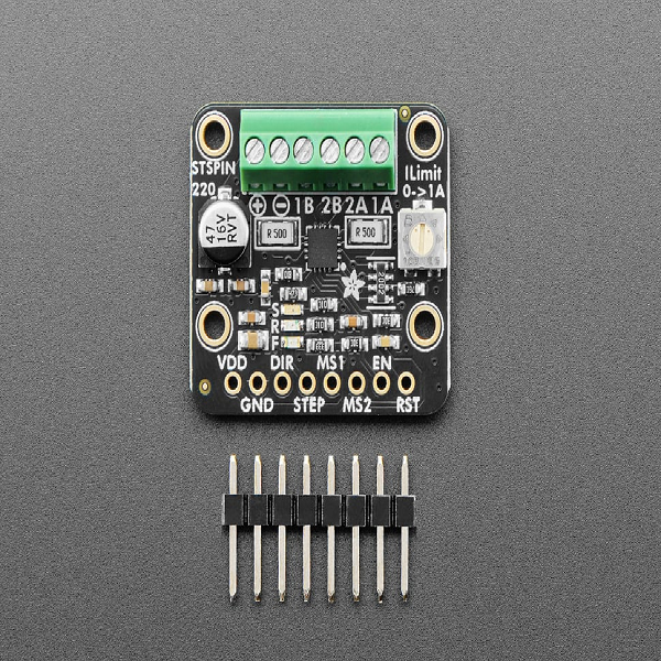
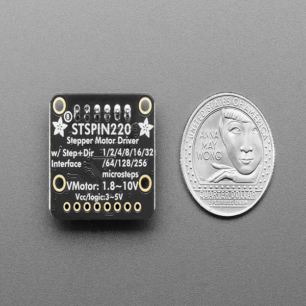
All you need is two output pins: no timers, PWM, or a real-time microcontroller. Set the DIRection pin high or low to set the spin orientation. Then, toggle the STEP pin to take one step or microstep at a time. By default, the board is configured for 1/16 microsteps per toggle. However, if you want to connect the RESET pin and the two mode pins, you can set anywhere from 1, 1/2, 1/4, 1/8, 1/16, 1/32, 1/64, 1/128 or even 1/256! The microstep mode is determined by the DIR/STEP/MS1/MS2 pin states when coming out of reset. The step/microstep mode can be adjusted on the fly! LEDs on the DIR and STEP pins let you get visual feedback of your motor signal.
We stock quite a few of these "DIR/STEP" stepper drivers - each with it's strengths! Here's a quick comparison:
- A4988 - Classic low-cost chip! 8-35V at 2A per coil. Only up to 1/16 microstepping, doesn't 'silent step' so its noisier.
- TMC2209 - Super silent 3D printer fav! 5-28V at 2.8A peak per coil. Up to 1/256 microstepping, stallGuard, spreadCycle but some of the settings & special capabilities require using the UART-interface configuration.
- STSPIN220 - Great for lower voltages! 1.8-10V at 1.3A per coil. Up to 1/256 microstepping, GPIO-only needed for configuration.
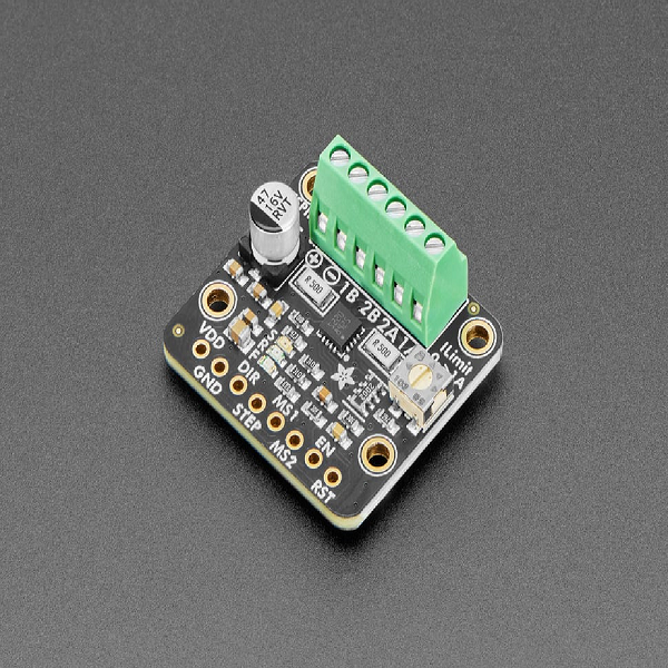
The STSPIN220 is a popular driver chip, especially for smaller/lower-voltage motor driving. Often it comes in "3D printer breakout" designs: those breakouts are great for plugging into motherboards but are a little tough to use for prototyping. Our version comes with terminal blocks for the motor power and stepper wires, plus nicely labeled pins for control and mounting holes.
This driver has built in current-limiting capability. To use the current limiting capability, twist the onboard potentiometer all the way to the right: we can get to up to 2A max. Note that the higher the current will heat up both the motor driver and stepper so you may need to add heatsinking to the chip. We don't include an heatsink, but you can get a tall ~80ºC/W or short ~90ºC/W heatsink to attach on top.
Features:
- STSPIN220 microstepping driver with translator and overcurrent protection
- Motor voltage from 1.8 to 10V
- Vdd/Logic voltage from 3V to 5V, use with anything from an Arduino-compatible or ESP32 to Raspberry Pi or other Single Board Computer
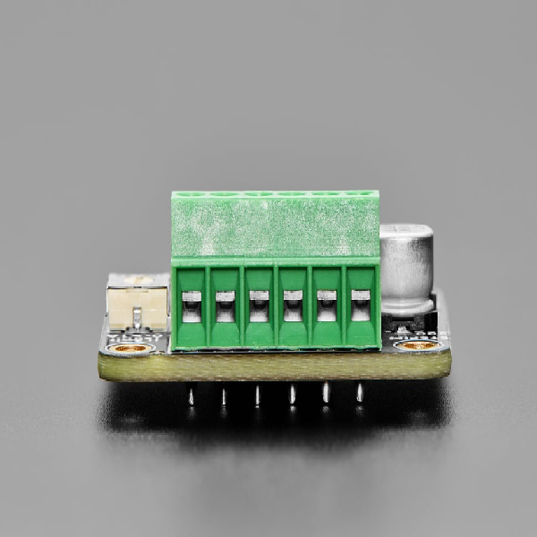
- Terminal screw block connections for easy VMotor power and 4-wire bi-polar stepper motor connection with 26-20AWG slots, 2.54mm / 0.1" spacing
- Control steppers using only two pins: DIRection and STEP
- Defaults to 1/16 microstep mode, change by setting DIR/STEP/MS1/MS2 pins and resetting (see STSPIN220 datasheet for pin configuration)
- Red and Green LEDs on DIR signal to let you know forward or backward motion
- Yellow LED on STEP to let you know that motor driver is being moved
- Reset and Enable control lines for low power / deactivation
- Potentiometer to set current limiting, up to ~1.3A
- 47uF 16V electrolytic capacitor on motor power
- Four mounting holes
Comes as one assembled and tested breakout, plus a small strip of header. You'll need to do some light soldering to attach the header to the breakout PCB. The Microcontroller, motors, and power supply are not included. You will need some sort of driver board that will toggle the DIR/STEP pins for you.
Product Dimensions: 27.0mm x 24.0mm x 10.0mm / 1.1" x 0.9" x 0.4"
Product Weight: 4.2g / 0.1oz


