

4972-POLOLU, TB67H453FTG (QFN) Single Brushed DC Motor Driver Carrier
The TB67H453FTG from Toshiba is an H-bridge motor driver IC that can be used for bidirectional control of one brushed DC motor at 4.5 V to 44 V. It can supply approximately 1.1 A continuous and has a current limit set to 2 A by default (with 5 V on SLEEP). The board’s holes are compatible with standard 0.1″ headers. Headers are not included with this product.
Features- Drives a single bidirectional brushed DC motor or two unidirectional brushed DC motors
- Motor supply voltage: 4.5 V to 44 V
- Output current: 1.1 A continuous (2 A default current limit)
- Supports 1.8 V to 5 V logic voltage (5.5 V max)
- Integrated current sensing and adjustable active current regulation
- Two current regulation mode options: cycle-by-cycle or fixed off time
- Three input control modes:
- Phase/enable (PH/EH)
- PWM (IN/IN)
- Independent half-bridge control
- Under-voltage lockout and protection against over-current and over-temperature
- Carrier board adds reverse-voltage protection
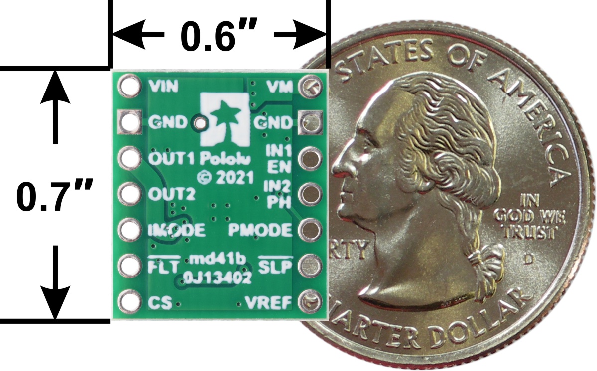
- Compact size (0.6″×0.7″)

| PIN | Default State | Description |
|---|---|---|
| VIN | 4.5 V to 44 V board power supply input. | |
| GND | Ground connection points for the motor and logic supplies. The control source and the motor driver must share a common ground. | |
| VM | Motor power access after reverse-voltage protection (can power other system components). | |
| OUT1 | Motor output 1. | |
| OUT2 | Motor output 2. | |
| EN/IN1 | LOW | Motor control input 1 (enable in PH/EN mode). |
| PH/IN2 | LOW | Motor control input 2 (direction in PH/EN mode). |
| PMODE | FLOATING | Selects control mode; latched on SLEEP enable. |
| SLEEP | LOW | Low-power sleep mode when low; outputs high-impedance. |
| VREF | Current limiting threshold reference voltage. | |
| IMODE | PULLED LOW | Selects regulation and protection modes. Default is cycle-by-cycle with automatic retry. |
| FAULT | FLOATING | Open-drain, active-low fault output. Requires external pull-up. |
| CS | Analog current-sense output (approx. 2.5 V/A default). |
Supply 4.5 V to 44 V to VIN. VM provides reverse-protected motor voltage. Apply 1.8 V to 5.5 V logic voltage to SLEEP to enable the driver.
The logic voltage on SLEEP affects VREF and the current limit threshold. This voltage can come from or be switched by the controlling device for sleep control.
The TB67H453 supports three control modes: PH/EN, IN/IN, and independent half-bridge. PMODE selects the control mode and is latched when SLEEP is enabled.
Phase/enable (PH/EN) mode

Setting PMODE low before enabling selects phase/enable mode: PH sets direction, EN receives PWM for speed. This drive/brake mode is simple and effective.
| Drive/brake operation (PMODE = 0) | ||||
|---|---|---|---|---|
| EN | PH | OUT1 | OUT2 | Operating Mode |
| 0 | X | L | L | Brake low |
| PWM | 1 | PWM | L | Forward at PWM speed |
| PWM | 0 | L | PWM | Reverse at PWM speed |
For locked-antiphase operation, apply PWM to PH and hold EN high. 0% = full reverse, 100% = full forward, 50% = stop.
PWM (IN/IN) mode

Set PMODE high before enabling to use IN/IN mode, which supports drive/brake and drive/coast operation without sleep mode.
| PWM control (PMODE = 1) | ||||
|---|---|---|---|---|
| IN1 | IN2 | OUT1 | OUT2 | Operating Mode |
| 0 | 0 | Z | Z | Coast |
| PWM | 0 | PWM (H/Z) | PWM (L/Z) | Forward coast |
| 0 | PWM | PWM (L/Z) | PWM (H/Z) | Reverse coast |
| PWM | 1 | L | Inverted PWM | Reverse brake |
| 1 | PWM | Inverted PWM | L | Forward brake |
| 1 | 1 | L | L | Brake low |
Independent half-bridge mode
Leaving PMODE floating enables independent half-bridge control. Refer to the TB67H453 datasheet for full implementation details.
Current sensingCurrent is sensed on the CS pin. The default configuration provides 2.5 V per amp. Adding a parallel resistor between CS and GND reduces this sensitivity.
Schematic


