

4971-POLOLU, TB67H453FNG Single Brushed DC Motor Driver Carrier
Overview
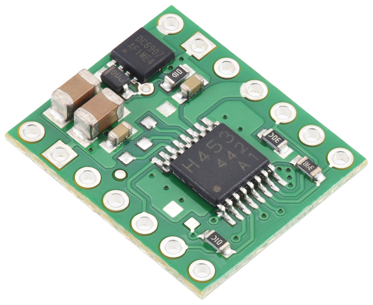
The TB67H453FNG from Toshiba is an H-bridge motor driver IC that enables bidirectional control of one brushed DC motor from 4.5 V to 44 V. It can supply approximately 1.3 A continuously, with a default current limit of 2 A when 5 V is applied to SLEEP. Since this board is a carrier for the TB67H453FNG, please refer to the TB67H453FNG datasheet for complete technical details. All surface-mount components, including the IC, are pre-soldered.
The board has 0.1″ header-compatible through-holes. Headers are not included but may be purchased separately. Wires can also be soldered directly for compact setups.
Features
- Drives one bidirectional brushed DC motor or two unidirectional motors
- Motor voltage: 4.5 V to 44 V
- Output current: 1.3 A continuous (2 A current limit by default)
- Logic voltage: 1.8 V to 5.5 V
- Integrated current sensing and active current regulation
- Two current regulation modes: cycle-by-cycle or fixed off-time
- Three input control modes:
- Phase/enable (PH/EN)
- PWM (IN/IN)
- Independent half-bridge control
- Protections: under-voltage lockout, over-current, and over-temperature
- Reverse-voltage protection (on carrier board)
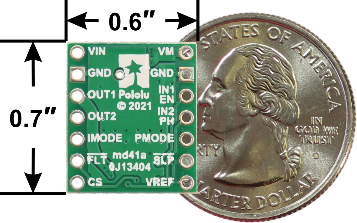
- Compact board size: 0.6″ × 0.7″
Using the Motor Driver
Pinout

| PIN | Default State | Description |
|---|---|---|
| VIN | – | 4.5 V to 44 V board power supply input. |
| GND | – | Ground for motor and logic. Control and driver must share common ground. |
| VM | – | Motor supply output after reverse-protection, usable for powering other components. |
| OUT1 | – | Motor output 1. |
| OUT2 | – | Motor output 2. |
| EN/IN1 | LOW | Motor input 1 (Enable in PH/EN mode). |
| PH/IN2 | LOW | Motor input 2 (Direction in PH/EN mode). |
| PMODE | FLOATING | Control interface select. Set LOW for PH/EN, HIGH for IN/IN, floating for half-bridge. Latched on SLEEP enable. |
| SLEEP | LOW | Puts driver in low-power sleep. Outputs go high impedance when LOW. |
| VREF | – | Reference voltage for current limiting (depends on logic voltage on SLEEP). |
| IMODE | PULLED LOW | Selects current chop and over-current response modes. Pulled to GND by 20 kΩ resistor. |
| FAULT | FLOATING | Open-drain, active-low fault output. Requires external pull-up. |
| CS | – | Analog current-sense output (~2.5 V/A). Resistor-parallel adjustment supported. |
The VIN pin takes the 4.5–44 V motor voltage. VM provides reverse-protected motor voltage to other devices. The SLEEP pin must be pulled high (1.8–5.5 V) to activate the driver. Note that the voltage on SLEEP affects VREF and hence the current limit.
Phase/Enable (PH/EN) Mode

Set PMODE LOW before enabling the driver to enter this mode. PH determines direction, and EN receives the PWM signal for speed control (sign-magnitude operation). Only drive/brake operation is available.
| Drive/brake operation (PMODE = 0) | ||||
|---|---|---|---|---|
| EN | PH | OUT1 | OUT2 | Mode |
| 0 | X | L | L | Brake low |
| PWM | 1 | PWM (H/L) | L | Forward/brake |
| PWM | 0 | L | PWM (H/L) | Reverse/brake |
This mode also supports locked-antiphase control: tie EN HIGH and apply a high-frequency PWM to PH. 50% duty cycle = stop; 0% or 100% = full speed reverse or forward.
PWM (IN/IN) Mode

Set PMODE HIGH before enabling to enter this mode. This allows drive/coast and drive/brake operation. The outputs can also be set high impedance without sleep.
| PWM control (PMODE = 1) | ||||
|---|---|---|---|---|
| IN1 | IN2 | OUT1 | OUT2 | Mode |
| 0 | 0 | Z | Z | Coast |
| PWM | 0 | PWM (H/Z) | PWM (L/Z) | Forward/coast |
| 0 | PWM | PWM (L/Z) | PWM (H/Z) | Reverse/coast |
| PWM | 1 | L | Inverted PWM | Reverse/brake |
| 1 | PWM | Inverted PWM | L | Forward/brake |
| 1 | 1 | L | L | Brake low |
Independent Half-Bridge Mode
Leave PMODE floating at enable time. Refer to the TB67H453 datasheet for detailed operation of this mode.
Current Sensing
The CS pin outputs an analog voltage (~2.5 V/A) representing motor current through low-side MOSFETs. This is based on a 2.49 kΩ resistor; additional parallel resistance reduces sensitivity.
Current Limiting
The driver supports active current limiting through current chopping. The default mode is cycle-by-cycle, set by the onboard 20 kΩ pull-down on IMODE. The limit is VREF divided by sense sensitivity. With SLEEP = 5 V, current limit ≈ 2 A. Reduce current by pulling VREF down or adjust sensitivity via CS. Connect CS to GND to disable current limiting (protection still limits at ~3.5 A).
Schematic


