
The module has a working frequency range of 2.4GHZ, and GFSK modulation mode.
The maximum transmission power is 4db, with a maximum transmission distance of 60 meters making BLE faster and easier to add to projects.
Quick Spec
- Working Frequency: 2.4 GHZ
- Transmission Power: 4db (maximum)
- Communication Interface: UART
- Operating Voltage: 1.8V - 3.6V
- Operating Temperature: -40℃ ~ +80℃
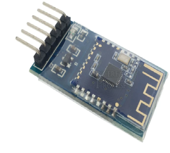
- Antenna: Built-in PCB antenna
- Reception Sensitivity: -97dBm
- Transmission Distance: 60 m
- Support master-slave: Slave
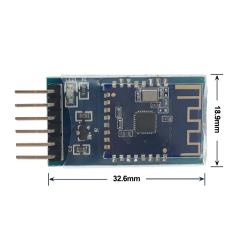
- Dimensions: 19.6 x 14.94 x 1.8mm
- Bluetooth Version: BLE 5.0 (Compatible with BLE4.0, BLE4.2)
- Awakening Current State: 800uA (Transmission)
- Sleep Status of Current Light: <50uA (Transmission)
- Deep Sleep Current: 9uA (Not transmission)
- Energy Saving Instruction Parameter: The configuration of the power-down data parameters is saved
- SMT Welding Temperature: <260℃
- Rf-TX / RX peak Current: 5mA
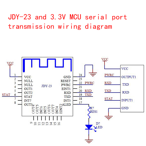
Pinout
- PWRC
- Sleep wake-up pin, active low
- In the connected state, the AT command can be pulled
- Low through the PWRC pin.
- VCC: Power Supply (3.6-6V)
- GND: Ground
- TXD: Serial output pin (TTL level)
- RXD: Serial input pin (TTL level)
JDY-23 Serial port of the module sends AT command It must add \r\n. Commands are case sensitive
|
Sequence |
Instructions |
Effect |
Master |
Default |
|
1 |
AT + VER |
Version number |
S |
JDY-23-V2.1 |
|
2 |
AT + RST |
Soft reset |
S |
- |
|
3 |
AT + DISC |
Unplugged command |
S |
- |
|
4 |
AT + STAT |
00 |
- |
- |
|
5 |
AT + MAC |
MAC address |
S |
- |
|
6 |
AT + BAUD |
Baud Rate |
S |
9600 |
|
7 |
AT + SLEEP |
Sleep |
S |
|
|
8 |
AT + NAME |
Transmission name |
S |
JDY-23 |
|
9 |
AT + |
Starting sleep or wake up |
S |
0 |
|
10 |
AT + ADVIN |
Transmission interval |
S |
1 (200 mS) |
|
11 |
AT + |
Slave mode or IBEACON work mode |
S |
0 |
|
12 |
AT + IBUUID |
UUID of IBEACON |
S |
FDA50693A4E24FB1AFCFC6EB07647825 |
|
13 |
AT + BIG |
PRINCIPAL of IBEACON |
S |
10 |
|
14 |
AT + |
IBEACON of MINORS |
S |
7 |
|
15 |
AT + IBSING |
Calibration signal at 1 meter |
- |
0x32 |
|
16 |
AT + ALED |
LED indicator switch transmission |
- |
1 |
|
17 |
AT + IBPWR |
IBEACON SINGING value |
S |
50 |
|
18 |
AT + |
Reset |
S |
- |
|
19 |
AT + POWR |
Transmission power |
S |
8 |
|
20 |
AT + ENLOG |
Serial switch output LOG |
S |
0 |
|
21 |
AT + MTU |
Set the serial port for the APP to send a long number of packets |
S |
1 |
|
22 |
AT + BATT |
Battery set |
S |
0 |
Pin Description

|
Pin # |
Features |
Description |
|
1 |
VCC |
Power supply (1.8-3.6 V) |
|
2 |
NULL |
No |
|
3 |
NULL |
No |
|
4 |
OUTPUT1 |
IO1 output pin (high and low level control APP support) |
|
5 |
OUTPUT2 |
IO2 output pins (support APP control of high and low levers) |
|
6 |
STAT |
The status of the pin connection, connected high, not connected to low |
|
7 |
INPUT7 / PWM4 |
INPUT7 mode: For the input pin, the APP can read the status of this pin. |
|
8 |
OUTPUT3 |
IO3 output pin (high and low level control APP support) |
|
9 |
OUTPUT4 |
IO4 output pin (high and low level control APP support) |
|
10 |
OUTPUT5 |
IO5 output pin (high and low level control APP support) |
|
11 |
INPUT6 / PWM3 |
INPUT6 mode: For the input pin, the APP can read the status of this pin. |
|
12 |
INPUT5 / PWM2 |
INPUT5 mode: For the input pin, the APP can read |
|
13 |
OUTPUT6 |
IO6 output pins (high and low level control APP support) |
|
14 |
OUTPUT7 |
IO7 output pin (high and low level control APP support) |
|
15 |
INPUT4 |
For the input pin, the APP can read the status of this pin. |
|
16 |
EINT2 |
Input pin interrupt (in connected state, press to actively send IO status to APP) |
|
17 |
ALED |
Pin transmission indicator |
|
18 |
INPUT3 / PWM1 |
INPUT3 mode: For the input pin, the APP can read the state of thi pin. |
|
19 |
TXD |
Serial output pin (TTL level) |
|
20 |
RXD |
Serial input pin (TTL level) |
|
21 |
EINT1 |
Input pin interrupt (in connected state, press to actively send IO status to APP) |
|
22 |
PWRC |
Sleep wake-up pin, active low. In the connected state, the AT command can be pulled Low through the PWRC pin. |
|
23 |
RTD |
Reset pin, active low |
|
24 |
GND |
Power land |


