
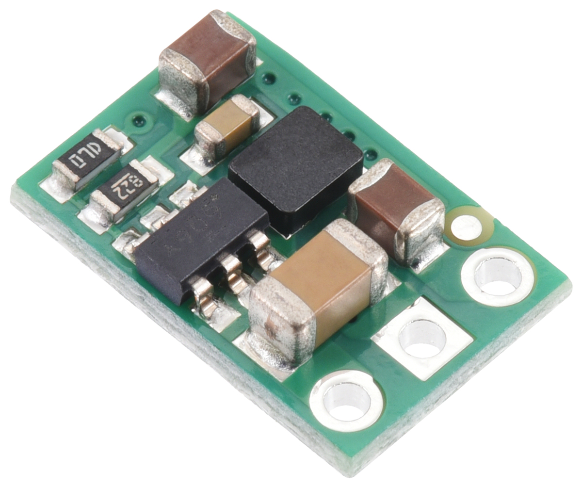
5433-POLOLU, 5V, 500mA Step-Down Voltage Regulator D45V5F5
The D45V5Fx family of synchronous buck (step-down) voltage regulators generate lower voltages from input voltages up to 65 V, supporting maximum continuous output currents between 400 mA and 700 mA depending on the input/output voltage combination. These are switching regulators (SMPS/DC-to-DC converters), offering much higher efficiency than linear regulators, especially when the input-to-output voltage difference is large. These boards include short-circuit and thermal shutdown protection but do not have reverse voltage protection.
Features
- Input voltage: 5.2 V to 65 V (subject to dropout voltage)
- Output voltage: 5 V ±4%
- Maximum output current: 700 mA (see current graph below)
- Fixed 1.1 MHz switching frequency under normal loads
- Low quiescent current: < 0.2 mA for most operating conditions
- Short-circuit and over-temperature protection
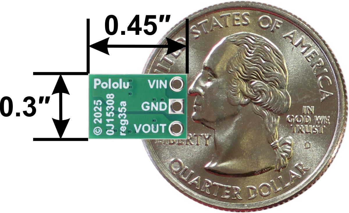
- Compact size: 0.3″ × 0.45″ × 0.11″ (7.6 mm × 11.4 mm × 2.8 mm)
- Weight: 0.4 g
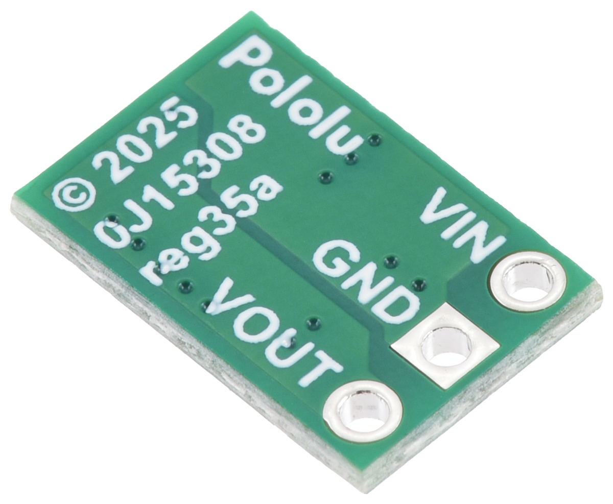
Connections

This regulator has three connections: input voltage (VIN), ground (GND), and output voltage (VOUT).
VIN powers the regulator. Voltages between 4 V and 65 V can be applied, but VIN must exceed VOUT by at least the dropout voltage (which increases with load).
The connections are labeled on the PCB back side and spaced 0.1″ apart for breadboard compatibility. You can solder wires or 0.1″ header pins directly to the board. Note: Header pins are not included.

Maximum Continuous Output Current
The achievable output current depends on input voltage, ambient temperature, air flow, and heat sinking. The graph below shows the maximum continuous current at room temperature with no additional cooling.

Quiescent Current
This is the current the regulator uses to power itself. The graph below shows quiescent current versus input voltage for various versions.

Typical Dropout Voltage
The dropout voltage is the minimum difference required between input and output to maintain regulated output. This value increases with output current. The graph below shows dropout voltage curves for this regulator family.

LC Voltage Spikes
Initial current rushes can cause voltage spikes higher than the applied input, especially with long wires or high inductance supplies. Spikes over 65 V may destroy the regulator. In tests, input voltages around 30 V caused spikes approaching 65 V with 1 m leads.
Warning: If using input voltages above 30 V or if your setup has high inductance, solder a 33 μF or larger electrolytic capacitor between VIN and GND close to the regulator.


