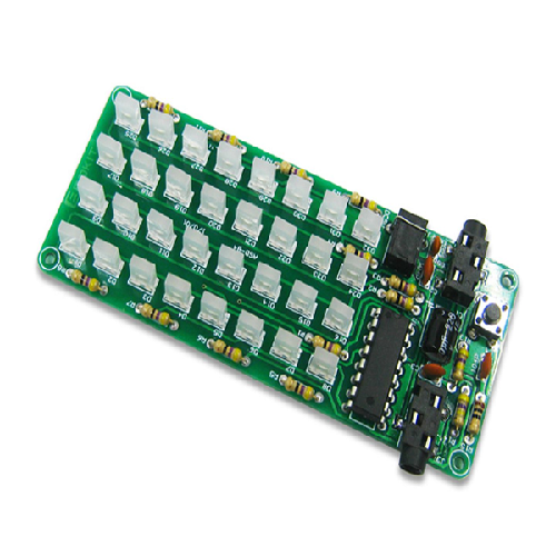
This is a 5 Volt audio spectrum level indicator DIY assembly with 4 rows of 8 LED lights to monitor audio signal function and intensity.
|
1.Features:
1> High sensitivity;
2> Low power;
3> Wide operating voltage range;
4> Low power consumption;
5> DIY design;
6> Colorful display;
7> Mode adjustable;
2. Parameters:
|
No.
|
Parameter
|
Value
|
|
1
|
Model
|
ASD-84
|
|
2
|
Standby current
|
Less than 1mA
|
|
3
|
Soldering difficulty Level
|
Easy
|
|
4
|
Working voltage
|
DC 5V
|
|
5
|
Display LED
|
8*4
|
|
6
|
Display color
|
Red + Blue
|
|
7
|
LED Size
|
2*5*7
|
|
6
|
PCB Size
|
94*39.5mm
|
3. Instructions:
Step 1: Complete installation.
Step 2: Connect audio;
Step 3: Apply DC 4-9V voltage;
Step 4: Adjust working mode;
Step 5: Test and use.
4. Mode setting:
|
Mode
|
Set Method
|
Remarks
|
|
Factory Testing Mode
|
Press button S1 before Power on
|
Used to monitor all LED on functions
|
|
Fast Flashing Mode (3)
|
Short press S1 less than 1second
|
The refresh frequency is very fast
|
|
Medium Flashing Mode (2)
|
Short press S1 less than 1second
|
The refresh frequency is general
|
|
Slow Flashing Mode (1)
|
Short press S1 less than 1second
|
The refresh frequency is slow
|
|
High Sensitivity Mode (H)
|
Long press S1 more than 2second
|
It can detect weaker audio signals
|
|
Medium Sensitivity Mode (B)
|
Long press S1 more than 2 seconds
|
It can detect general audio signals
|
|
Low Sensitivity Mode (L)
|
Long press S1 more than 2 seconds
|
It can filter more interference audio signals
|
5. Verification
- Please ensure that all components are positioned in correct designation with polarity in right direction.
- Please verify that each component is properly soldered.
- The soldering iron can't touch the components for a long time, otherwise the components will be damaged because of the high temperature.
- It is recommended to use a stable power supply, otherwise it may interfere with the audio signal output.
|
NO.
|
Component Name
|
PCB Designations
|
Parameter
|
Quantity
|
|
1
|
Metal Film Resistor
|
R15
|
10 ohm
|
1
|
|
2
|
Metal Film Resistor
|
RX1-RX4, RY5-RY12
|
47 ohm
|
12
|
|
3
|
Metal Film Resistor
|
R13-R14
|
470 K ohm
|
2
|
|
4
|
Ceramic Capacitor
|
C5
|
0.001uF 102
|
1
|
|
5
|
Ceramic Capacitor
|
C2-C4
|
0.1uF 104
|
3
|
|
6
|
Electrolytic Capacitor
|
C1
|
220 uF
|
1
|
|
7
|
Red LED
|
D1-D16
|
2*5*7mm
|
16
|
|
8
|
Blue LED
|
D17-D32
|
2*5*7mm
|
16
|
|
9
|
Audio Socket
|
J2, J3
|
SMD3P
|
2
|
|
10
|
Power Socket
|
J1
|
DC3.5
|
1
|
|
11
|
WD1084
|
U1
|
DIP-16
|
1
|
|
12
|
Button
|
S1
|
6*6*5
|
1
|
|
13
|
USB to DC Cable
|
To J1
|
100cm
|
1
|
|
14
|
Audio Cable
|
To J2
|
100cm
|
1
|
|
15
|
PCB
|
ASD-84
|
94*39.5mm
|
1
|
|
|
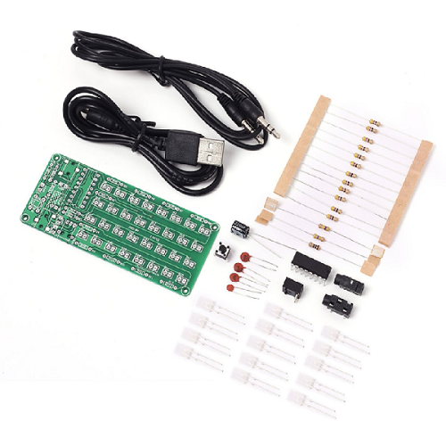
7. Installation tools needed (not supplied):
1>. Soldering iron;
2>. Multimeter;
3>. Solder wire;
4>. Iron stand;
5>. Diagonal cutting pliers;
6>. Tweezers;
7>. Long nose pliers;
8>. Desoldering Suction pump;
9>. Tip Cleaning sponge;
10>. Screwdriver set.
AK-ASD-84 (ADS-84.pdf, 11,296 Kb) [Download]