Waterproof Ultrasonic Module JSN-SR04T-3.0 Distance Measuring Transducer Sensor, for Arduino DIY Electronic Kit
The new version of SR04T-3.0 release solves the problem of blind data jumps and improves the stability of the product. JSN-SR0T4-3.0 ultrasonic ranging module can provide 21cm-600cm non-contact distance sensing function, ranging accuracy can be as high as 3mm; the module consists of an ultrasonic sensor and control circuit integrated with transceiver. The usage of mode one is compatible with our HC-SR04 module.
Features:
1. Small size and easy to use:
2. Low voltage and low power consumption:
3. High measurement accuracy;
4. Strong anti-interference;
5. Integrated closed waterproof probe with wire, suitable for wet and harsh measurement occasions.
Product parameters:
Working voltage: DC: 3.0V-5.5V
Working current: less than 8mA
Probe frequency: 40kHz
Longer range: 600cm
Shorter range: 20cm
Long range accuracy: ±1cm
Resolution: 1mm
Mileage angle: 75 degrees
Input trigger signal:
1. TTL pulse above 10uS;
2. Serial port sending command 0X55
Output echo signal Output pulse width level signal, or TTL
Wiring:
3-5. 5V (power +)
Trig (Control) RX
Echo (output) TX
GND (power-)
Working temperature: -20-+70 degree
Function description: 6 modes.
Mode 2: M2 short connection is serial port controlled output
Mode 1: M1 short connection is automatic serial output
Mode 0: Mode floating = trigger pulse width output (factory default mode)
Mode 3: Mode welding 200K = automatic distance pulse width output
Mode 4: Mode welding 360K = low power pulse width mode output
Mode 5: Mode welding 470K = switch mode output
Mode 0: Mode=floating high level (PWM) pulse width output
1) Pin Definition
Trig: trigger control
Echo: High level pulse width output
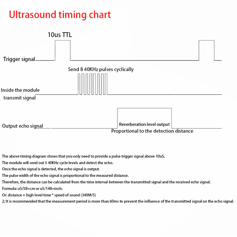
(1) Basic working principle: (1) Use IO port TRIG to trigger ranging, and give a high level signal of at least 10us.
(2) The module automatically sends 8 square waves of 40khz, and automatically detects whether there is a signal return;
(3) There is a signal return, output a high level through the IO port ECHO, and the duration of the high level is the time from the launch of the ultrasonic wave to the return. Test distance at room temperature = (high level time * speed of sound (348M/S))/2;
(4) After the module is triggered to measure the distance, if no echo is received (the reason is beyond the measured range or the probe is not facing the measured object), the ECHO port will automatically change to low level after 40MS, marking this time. The measurement ends, whether successful or not.
(5) The LED is on at the end when powered on, and only when the trigger signal is given to the TRIG pin. The flashing frequency of the LED is synchronized with the trigger period, indicating that the module has received the correct command to enter the working state.

Mode 1: Mode=open means no soldering. The mode is explained as follows
Basic working principle:
(1) Adopt IO port TRIG to trigger ranging. Present a high level signal of at least 10us.
(2) The module automatically sends eight 40khz square waves and automatically detects whether a signal returns;
(3) When a signal returns, a high level is output through the IO port ECH0. The duration of the high level is the time from the transmission of the ultrasonic wave to the return. Test distance height = (high level time * speed of sound (348M/S))/2.
(4) After the module is triggered for ranging, if the echo cannot be received (the reason exceeds the measured range or the probe does not face the measured object), the ECHO port will automatically become low after 40MS, marking this time The measurement ends, regardless of success.
Mode 2: Mode=47K (or directly short M1 bit) UART automatic output
The UART automatic output mode outputs the measured distance value (hexadecimal number) according to the UART communication format. This mode does not require an external trigger signal. The module can automatically measure every 100ms. The TX pin outputs the measured distance value after each measurement is completed.
Mode 3: Mode=120K (or short M2 bit directly) UART controlled output
The UART controlled output method outputs the measured distance value (hexadecimal number) according to the UART communication format. In this method, the trigger command oX55 signal needs to be added to the RX pin. The module measures once every time the command is received. The foot outputs the measured distance value. The command trigger cycle should be greater than 60ms.
Mode 4: Mode=200K high level (PWM) pulse width automatic output
Under the pulse width PWM automatic output, the module automatically measures at a period of 200ms, and outputs a pulse width high level corresponding to the distance after the measurement. Calculating distance mode reference mode 1.
Mode 5: Mode=360K low power consumption (PWM) high level pulse width controlled output
In low-power mode, the module's shut-down dog is disabled. This module is suitable for battery-powered users. The static power consumption is less than 70UA. The working distance measurement method is the same as mode 1.
Mode 6: Mode=470K switch output
The module will set a threshold value at the factory, the default is 1.5 meters. The module performs ranging every 200ms. When the detected distance value of the target is less than the set threshold, the Echo pin outputs a high level. The currently detected distance value is greater than the set threshold, and the Echo pin outputs a low power. In order to improve the stability, the factory defaults that the distance detected by the target for two consecutive times is less than the set threshold. Signal, no driving ability. Transistor drive relays should be added during application.


