

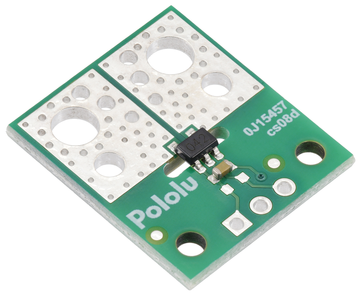
5454-POLOLU, ACS37042KLHBLT-010B3 Current Sensor Compact Carrier -10A to +10A, 3.3V
Hall effect-based, electrically isolated current sensor in a 5-pin SOT-23 package with approximately 1.6 mΩ current path resistance and 150 kHz bandwidth.
Features:
- Hall effect-based sensor with electrically isolated current path allows insertion anywhere in the current path, suitable for applications requiring galvanic isolation.
- Low primary current path resistance (1.6 mΩ), minimizing power loss.
- Differential Hall sensing reduces susceptibility to uniform external magnetic fields.
- High-bandwidth 150 kHz analog output proportional to AC or DC current.
- Less than 5 µs response time.
- Output is not ratiometric, offering improved immunity to noisy power supplies.
- Integrated temperature compensation improves accuracy across full temperature range.
- Automotive-grade temperature range: -40°C to 125°C.
- Available on compact 0.7″ × 0.8″ and micro 0.3″ × 0.4″ carrier boards with 0.1″-pitch breadboard-compatible connections.
- Higher isolation rating in ACS37042 IC; carrier PCB includes routed slots for improved creepage distance.
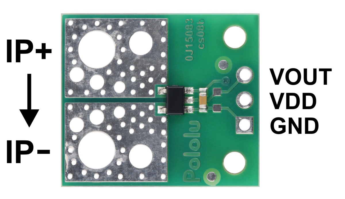
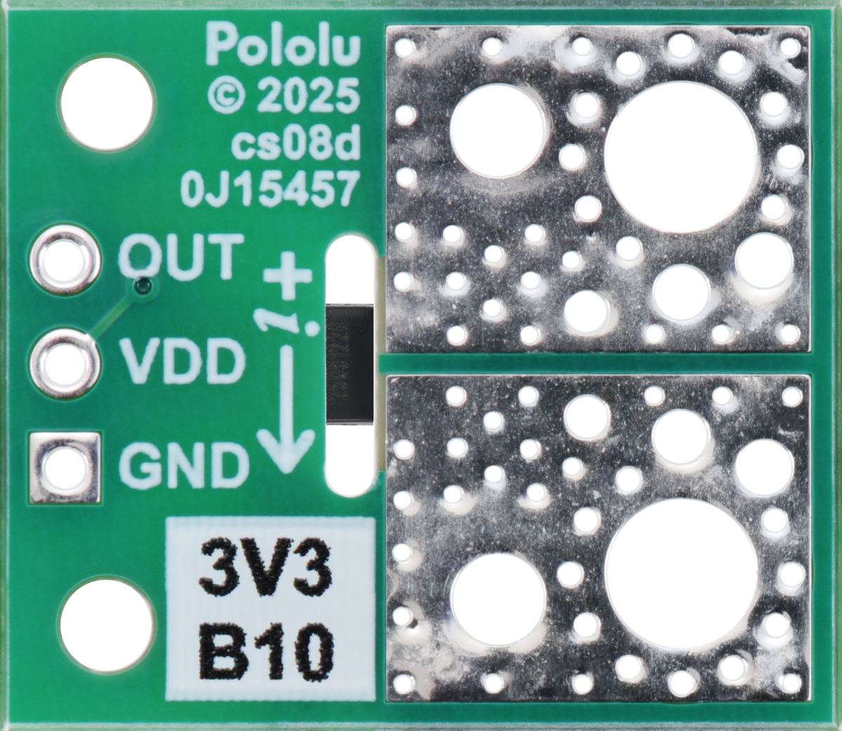
Making connections to the board:
You can insert the board into your current path in several ways. For high-current use, wires can be soldered directly to the largest through-holes, or solderless ring terminal connectors may be used. The largest holes accommodate 10 AWG wire or #6/M3.5 screws; the second-largest fit 14 AWG wire or #2/M2 screws. Additional holes with 0.1″, 3.5 mm, and 5 mm spacing support male headers or terminal blocks, though these are not recommended for high-current applications.


Isolation rating and board creepage considerations:
The ACS37041 and ACS37042 differ in isolation voltage ratings: 100 VRMS and 285 VRMS, respectively. The ACS37042 carrier PCBs have routed slots to increase creepage distance from 1.6 mm to 3.0 mm. As a guideline, FR4 PCBs require about 1 mm creepage per 100 VRMS of isolation. These boards are not certified to specific safety standards.
Warning: This product is generally intended for use below 30 V. Application images (e.g., on breadboards) are for low-voltage contexts. Higher voltage use is possible but should only be undertaken by qualified individuals with proper training and equipment.
Schematic:


