

5410-POLOLU, ACS37800KMACTR-030B3-I2C Power Monitor Carrier with Secondary I²C Isolation
This board is an integrated solution for monitoring voltage, current, power, and other parameters in AC and DC systems featuring Allegro’s ACS37800KMACTR-030B3-I2C isolated power monitoring IC. It provides bidirectional current measurements from −30 A to +30 A and can be configured to measure voltages up to 480 VRMS nominal (up to ±980 V peak). Our carrier board adds secondary isolation to the sensor’s I²C interface for additional safety and measurement accuracy.
Features:
- Measures voltage and current, both RMS and instantaneous
- Works in single-phase AC and DC systems
- Automatic zero-crossing detection and averaging
- Calculates active, reactive, and apparent power, as well as power factor
- 1 kHz bandwidth
- Hall effect-based current sensor with electrically isolated current path
- Sensor can be inserted anywhere along the current path
- Differential Hall sensing rejects errors from common-mode fields (e.g. Earth’s magnetic field)
- Low conductive path resistance (0.85 mΩ in ACS37800, PCB uses 2 oz copper)
- Board includes resistor network with isolation and sense resistors for measuring voltage
- Three configurable voltage measurement ranges optimized for 120 VAC, 240 VAC, and 480 VAC
- 1206-size, high-voltage-rated resistors on input voltage dividers
- Interface: I²C, using JST SH-style 4-pin connectors or 0.1″-pitch pins
- User configuration of the IC stored in on-chip EEPROM
- Programmable over-current, under-voltage, and over-voltage detection thresholds
- Compact 1.9″ × 1.8″ board size with a variety of connection options
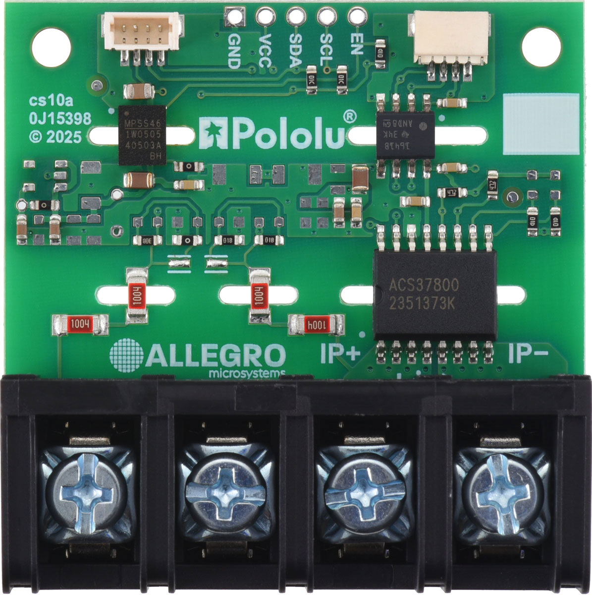
- Optionally available with terminal block already soldered
- Routed slots for higher creepage
- Secondary isolation for I²C signals and logic power provides additional safety and measurement accuracy
Using the Sensor:
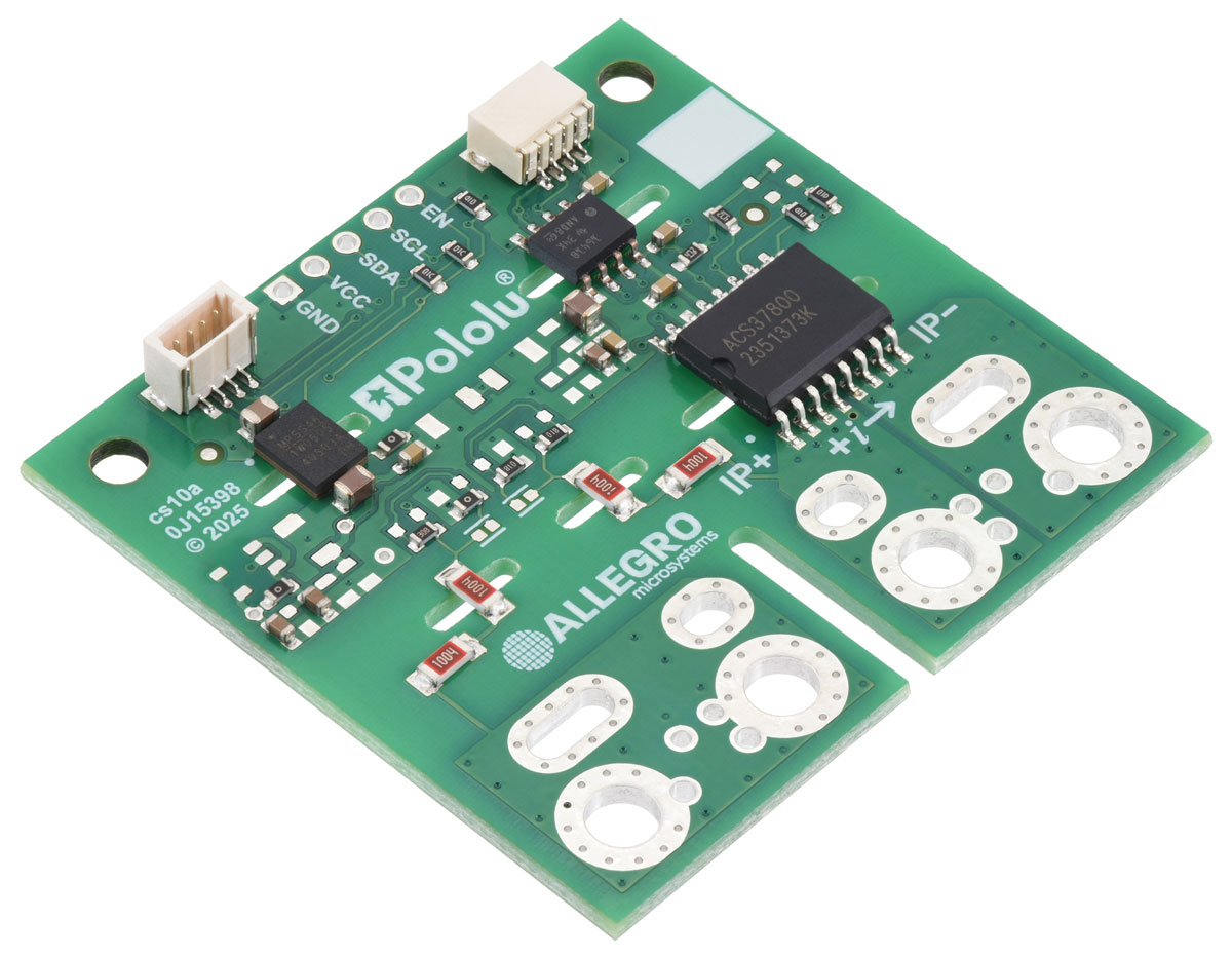
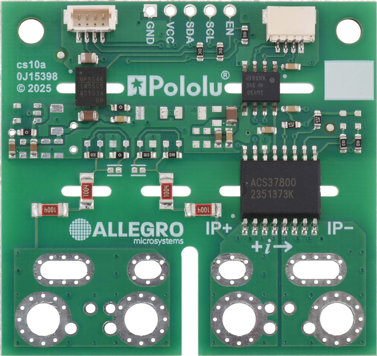
The ACS37800 measures current flowing from the IP+ to the IP− connection points. These are labeled on the board’s top silkscreen, which also shows the direction interpreted as positive current flow with a +i arrow. It measures voltage between IP+ and the connection points labeled V− on the schematic. The left-side through-holes are all electrically connected, so a convenient wiring method is to attach the power supply to the inner set and the load to the outer set.

For DC systems, following the polarity shown results in positive current readings when current flows from the supply to the load. For AC systems, polarity is less critical but still affects instantaneous readings.
The sensor’s logic side has four required connections: VCC, GND, SCL, and SDA. These can be made using JST SH-style 4-pin connectors (compatible with Qwiic and STEMMA QT) or 0.1″ pitch through-holes suitable for headers and breadboards.

The default I²C address is 0x60 (0b1100000), which can be reprogrammed via EEPROM. A logic supply of 3 V to 5.5 V should be applied to VCC. This also powers the on-board DC-DC converter, suppl


