

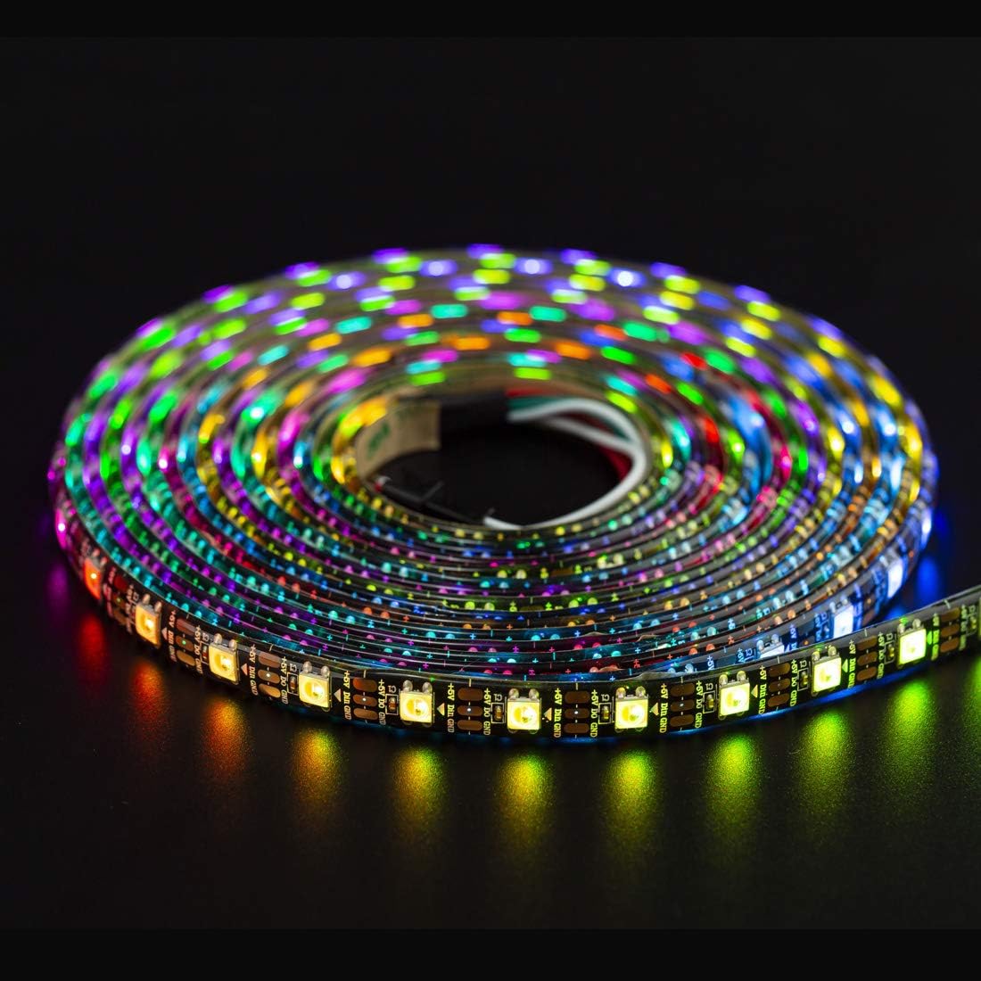

1 Meter, 60 LEDs 5VDC SK6812/WS2812B IP65 RGBCW (Cool White) STRIP – BLACK PCB
Specifications:
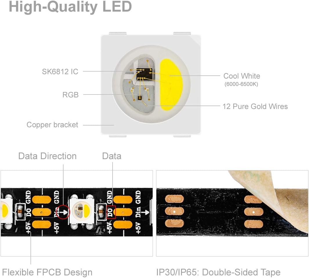
- LED source: 5050SMD RGBW built-in SK6812 chipset
- LED type: SMD5050
- 2 pin wire, Red line(+), White line(-); never connect directly the 110/220V AC
- IC: 1 IC drives, 1 led chip
- IC type: SK6812
- Voltage(DC): 5V
- Power: 18W/Meter
- Grey Grade: 256
- PCB color: Black
- Waterproof Grade: IP65 (Waterproof in Silicon Coating)
- Length: 1 meter
- Wire identification: Vcc = Red, GND = White, DAT = Green
- Note: There is a 3M self-adhesive tape at the back-side. You can install easily.
The package only includes the LED strip. Required: 5-volt power supply (not included) & LED controller (not included).
Connection is easy. The strip comes with two bare wires already attached to it. Connect the bare wires to the 368-ADA(not included) screw terminal, which in turn connects to our DC-5400-2.1 (5V power supply not included). See the Product Connection diagram.

How to get started:
Before you get started you will need the following material not included in the package, sold seperately:
- ABRA Arduino Nano V3.0 Compatible- ATmega328P (ABRA#: ABRANANO) OR ABRA Atmega328P Microcontroller Board Compatible with Arduino Uno R3 - (ABRA#: ABRAUNO)
- Any Breadboard (ABRA#: ABRA-6)
- A capacitor preferably 1000 microfarad and voltage of at least double the power supply of 5V DC (ABRA#: 1000R10 or ABRA#: 1000R16)
- 330 ohm resistor and a power of minimum of atleast 1/2W (ABRA#: R1/2-330)
- Logic level converter (NOT USED IN THIS EXAMPLE)
One way to light up the LED strip is using an Arduino. For this example, an arduino nano V3.0 Compatible - ATmega328P (Abra #: ABRANANO) will be used to explain how to light up the LED strips. What you will need is a breadboard, a capacitor (1000uF in this scenario, can be purchased at Abra), a 330ohm resistor (also can be purchased at Abra) and jumper wires male to male. The diagram below illustrates how to perform the connections. Please note that the longer leg of the capacitor is connected to the positive. And the shorter leg is connected to the negative.

Also, please do not connect to the power outlet yet. That will be at the end.
Next step, will be to open Arduino IDE and then go to "manage library" and install adafruit Neopixel. Once thats complete, you must set up the IDE to the following by selecting Tools and configuring board, processor and port. In this example, the board will be Arduino Nano, the processor will be ATmega328P, port will be COM10 if not it will be a port that is displayed when connected to the computer, before connect, check the port select options, and whatever is there, by default COM1 and COM4 are not the port for the arduino as its not connected. When connected a port with a COM and number will appear, once it appears, please select that. You can then proceed to doing a strand test. To do a strand test, you must select file, then navigate to examples which will open up a list of options, next you will select adafruit neopixel followed by strandtest and a source code will upload. For this product you must make the following changes to the code illustrated below to make the product work. Edit the code so that NEO_GRB is edited to NEO_RGBW as per the product you bought and as shown on the image below.
Default code:

Modified code:

For reference:
Arduino IDE link: Arduino IDE download link


