
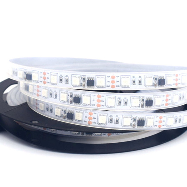
5 Meters, 150 LEDs 12VDC Addressable IP67 RGB STRIP – White PCB
This 5 Meters Strip is awesome. Unlike our 12V strips that use RF controls and can only drive the entire strip with Red, Green or Blue at one instance; this product is addressable allowing the user to control each individual pixel. This runs at 12VDC, so you might want to pick up a power supply designed for these strips at 12VDC or DC barreled Jack power supply at 12VDC. Every three pixels draw approximately 60mA on white, so you might want to calculate the total amount of LEDs you have in mind and find a power supply with a sufficient amount of current to supply them. This 5 meters strip can cut and use it separately. It also comes with adhesive at the back for placing on required mounts.
This strip comes in an IP67 waterproof (resistant) rating so the product is encased in a silicone sealed tube to prevent water from leaking in. This Strip is controlled by LPD8806 and you can daisy chain more strips if you feel like it and provide the required current.
Specifications:
- LED TYPE: RGB WS2811
- Viewing angle: 120°
- Operating Voltage: 12V
- Power:36W
- LED quantity: 30 LEDs/m, 150 LEDs
- Operating Temperature: 20ºC to 50ºC
- Dimensions : 500 x 1 x .2 cm (L x W x D)
Kit includes:
- 5Meters RGB LED strip
To get started using a pre-programmed controller, you will need the following parts:
- ABRA#: LED-STRIP-22(Included) - 5 Meters, 150 LEDs 12VDC Addressable IP67 RGB STRIP – White PCB
- ABRA#: LED-STRIP-CONT5V(Sold separately) - 3 Button, Mini LED Controller for 5V DC to 24 DC Addressable LED Strips
Connection is straightforward. First on LED-STRIP-CONT5V, notice that there are bare wires color coded red and black, connect it to 368-ADA screw terminal, which in turn connects to your power supply DC-1203-2.1, 12V DC 3A. Once complete, connect the LED-STRIP-CONT5V to the data input of the LED strip. See the Product Connection diagram below.

To get started using a microcontroller in this example, an Arduino Uno will be used, you will need the following parts:
- ABRA#: LED-STRIP-22(Included) - 5 Meters, 150 LEDs 12VDC Addressable IP67 RGB STRIP – White PCB
- ABRA#: 7805T(Sold separately) - Transistor Positive voltage regulator 1A, 5V
- ABRA#: 470R25(Sold separately) - Electrolytic radial capacitor 470 uf, 25V
- ABRA#: 100R35(Sold separately) - Electrolytic radial capacitor 100 uf, 35V
- ABRA#: 1N4007(Sold separately) - General Purpose Rectifier 1A, 1000V (Diode)
- ABRA#: JW-75(Sold separately) - Jumper wires
- ABRA#: R1/2-330(Sold separately) - 1/2 Watt-330 ohm resistor
- ABRA#: ABRAUNO(Sold separately) - Atmega328P Microcontroller Board Compatible with Arduino Uno R3
- ABRA#: ABRA-6(Sold separately) - Breadboards 400 Tie Points
- ABRA#: DC-1203-2.1(Sold separately) - Power Supply Table Top Wall Adapter with (2.1mm connector)
Connection is straightforward. First on the data output end of the strip, notice that it comes with two bare wires already attached to it. Connect the bare wires to the 368-ADA screw terminal, which in turn connects to your power supply DC-1203-2.1, 12V DC 3A. See the Product Connection diagram below. Now whatever you do, do not connect the power supply yet to the power outlet.
Since the LED strip requires 12V, and the Arduino Uno can only handle 5V, you will need to design a voltage regulator on the breadboard. The diagrams below illustrates the connections necessary to design a voltage regulator in this example 12V DC to 5V and to finally light up the LED Strips.
Please note that the longer leg of the capactior is connected to the positive end whereas the shorter leg is connected to the negative end. Also, the gray color band on the diode denotes the cathode. Please see the diagram for voltage regulator and images below for accurate connections.


Next step involves uploading the code to the Arduino. Once again, do not connect the power supply to the power outlet yet. That will be all at the end.
Open/install Arduino IDE, once there, go to "manage library" and install FastLed By Daniel Garcia. Moving forward, connect the arduino Uno via the wired provided and make sure it is configured so that the code could be uploaded. By selecting "Tools", you must configure the board, processor and port. The Board is Arduino Uno, the processor is ATmega328P and the port should normally be the only option available, if not, another trick to select the correct port is by checking before connecting which ports are available, and once connected, check again, the one that shows up that wasn't there before is the port to be selected. Now that the microcontroller has been identified, you can proceed to load up the code. If you are using the newer version of Arduino IDE 2.3.3, then the correct board, processor and port should appear on the drop-down menu below the tools button and to the right of debug button.
In this example, using Arduino IDE, you will select ColorPalette file from the examples in FastLED. The steps are simple, you will select "File", then navigate to examples which will open up a list of options, followed by selecting FastLED. A list of options will be presented, and as previously mentioned please select ColorPalette. In the default code, it will only light up half the strip since on line 8, "#define NUM_LEDS 50" is coded that way. In order to light up all the strip, you must change 50 to 100. Either, you can play around with it, but based on this code, the range for that line is 0-100 where 1 is equal to 3 LEDs lighting up. Once thats complete you can go ahead and upload the code. Once uploaded, you can disconnect the arduino uno from the computer and then plug in the other end of the strip with the power supply to the power outlet.
For reference:
Arduino IDE link: Arduino IDE download link


