
5348-POLOLU A5984 Stepper Motor Driver Carrier, Fixed 750mA@5V / 500mA @3.3V
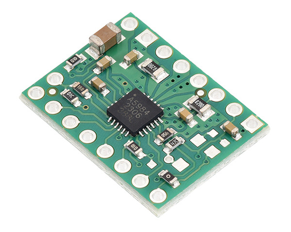
This is a carrier board for Allegro’s A5984 microstepping bipolar stepper motor driver. It offers eight different microstep resolutions (down to 1/32-step) and has over-current and over-temperature protection, and it features an adaptive decay algorithm that automatically optimizes the motor current waveform.
Features
- 8 V to 40 V supply voltage range (note: these are not recommended for use with 36V batteries, which can be well above nominal when fully charged)
- Simple step and direction control interface
- Eight different step resolutions: full-step with 100% current, modified full-step (71% current), 1/2-step with 100% current, modified 1/2-step (circular), 1/4-step, 1/8-step, 1/16-step, 1/32-step
- Adjustable and fixed current limit options let you choose an appropriate maximum current output, which lets you use voltages above your stepper motor’s rated voltage to achieve higher step rates
- Adaptive Percent Fast Decay (APFD) current control algorithm, also known as QuietStep, automatically adjusts the amount of fast decay to optimize the motor current waveform
- Over-temperature thermal shutdown, over-current protection, and under-voltage lockout
- 2 oz copper PCB for improved heat dissipation; 2-layer (green PCB) and 4-layer (blue PCB) options available
- Exposed solderable ground pad below the driver IC on the bottom of the PCB
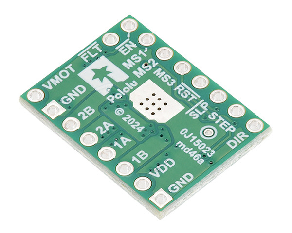
Diagram

Power connections
The driver requires a motor supply voltage of 8 V to 40 V (absolute max) to be connected across VMOT and GND. This supply should be capable of delivering the expected stepper motor current.
Motor connections
Four, six, and eight-wire stepper motors can be driven by the A5984 if they are properly connected.
Warning: Connecting or disconnecting a stepper motor while the driver is powered can destroy the driver. (More generally, rewiring anything while it is powered is asking for trouble.)
Step (and microstep) size
Stepper motors typically have a step size specification (e.g. 1.8° or 200 steps per revolution), which applies to full steps. A microstepping driver such as the A5984 allows higher resolutions by allowing intermediate step locations, which are achieved by energizing the coils with intermediate current levels. For instance, driving a motor in quarter-step mode will give the 200-step-per-revolution motor 800 microsteps per revolution by using four different current levels.
The resolution (step size) selector inputs (MS1, MS2, and MS3) enable selection from the eight step resolutions according to the table below. The driver defaults to full step with 100% current. For the microstep modes to function correctly, the current limit must be set low enough (see below) so that current limiting gets engaged. Otherwise, the intermediate current levels will not be correctly maintained, and the motor will skip microsteps.
| MS1 | MS2 | MS3 | Microstep Resolution |
|---|---|---|---|
| Low | Low | Low | Full step with 100% current |
| Low | Low | High | Half step with 100% current (also called non-circular half step) |
| Low | High | Low | 1/16 step |
| Low | High | High | 1/32 step |
| High | Low | Low | Modified full step (71% current) |
| High | Low | High | Modified half step (circular) |
| High | High | Low | 1/4 step |
| High | High | High | 1/8 step |
Control inputs and status outputs
The rising edge of each pulse to the STEP input corresponds to one microstep of the stepper motor in the direction selected by the DIR pin. Note that the STEP and DIR pins are not pulled to any particular voltage internally, so you should not leave either of these pins floating in your application. If you just want rotation in a single direction, you can tie DIR directly to VDD or GND.
The chip has thee different inputs for controlling its power states: RESET, SLEEP, and ENABLE. The RESET pin (RST) is floating by default; this pin must be high to enable the driver (it can be connected to the adjacent SLEEP pin or directly to a logic “high” voltage between 2 V and 5.5 V, or it can be dynamically controlled from a digital output of an MCU). The default state of the SLEEP (SLP) and ENABLE (EN) pins is to enable the driver (the carrier board pulls SLEEP up to VDD and pulls ENABLE down to GND). See the datasheet for more details.
The A5984 also features an open-drain FAULT (nFAULT) output that drives low whenever the driver detects an over-current fault. The carrier board pulls this pin up to VDD, so no external pull-up is necessary on the FAULT pin. Bringing RESET or SLEEP low clears a latched fault.
Current limiting
To achieve high step rates, the motor supply is typically higher than would be permissible without active current limiting. For instance, a typical stepper motor might have a maximum current rating of 1 A with a 5 Ω coil resistance, which would indicate a maximum motor supply of 5 V. Using such a motor with 9 V would allow higher step rates, but the current must actively be limited to under 1 A to prevent damage to the motor.
The A5984 supports such active current limiting, and this carrier has a fixed current limit set with on-board resistors. The current limit is proportional to the logic voltage, VDD; for this board, it is about 750 mA when VDD is 5 V or 500 mA when VDD is 3.3 V. You will typically want to choose a current limit that is at or below the current rating of your stepper motor.
Power dissipation considerations
The A5984 has a maximum current rating of 2 A per coil, and it can supply up to around 1 A continuous per coil on this carrier board without overheating under typical conditions (i.e. operation in open space at room temperature), so this version that has a fixed current limit of 750 mA or less will generally not need any special cooling to operate. However, additional cooling might be required for applications that limit heat dissipation, such as use in enclosed spaces or high ambient temperature conditions. Please note that measuring the current draw at the power supply will generally not provide an accurate measure of the coil current.
Schematic


