
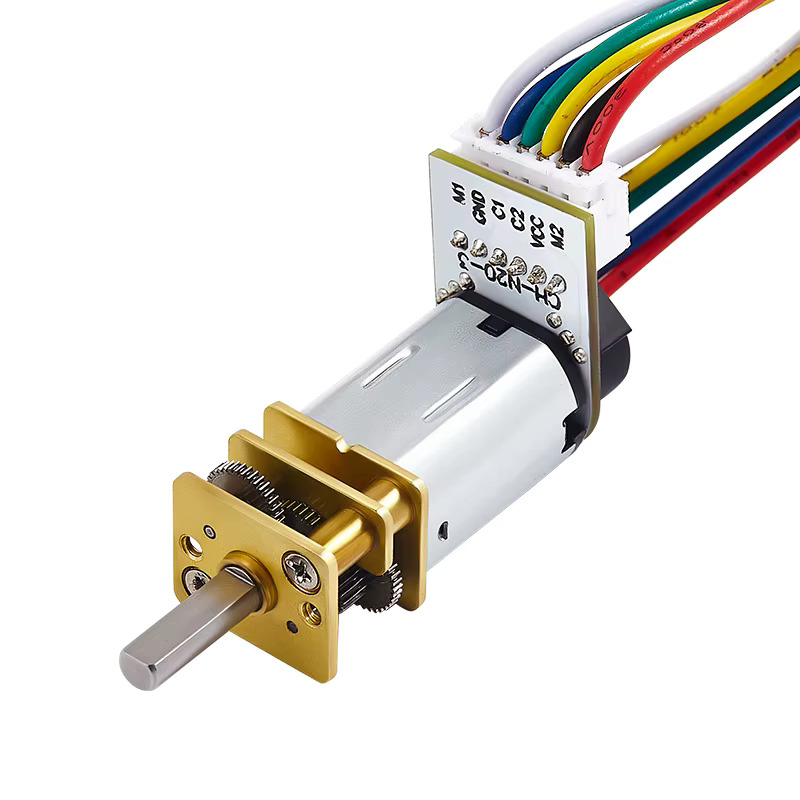
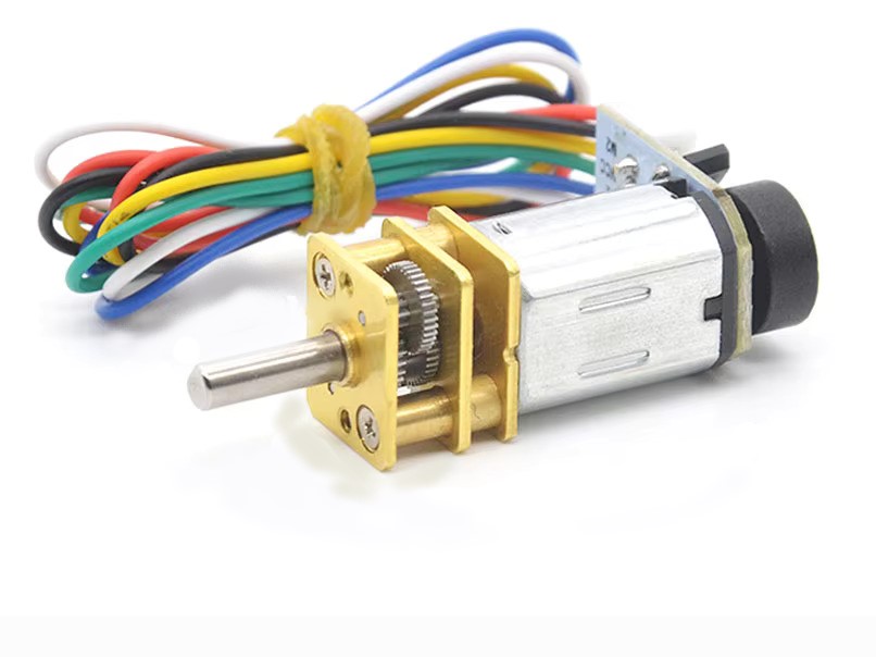

The JGA12-N20 6V 500 RPM Micro Permanent Magnet DC Gear Motor is a compact, high-speed DC motor with an integrated Hall-effect quadrature encoder. Its small footprint, metal gearbox, and encoder feedback make it ideal for robotics, automation, smart devices, and DIY electronics projects requiring precise speed and position control.
The motor supports bidirectional (CW/CCW) rotation and can be easily driven using common H-bridge motor drivers such as L298N, L9110S, or TB6612FNG. It is fully compatible with popular microcontrollers including Arduino, Raspberry Pi, and ESP32, with speed and direction controlled via PWM signals.
Motor Specifications
- Motor Type: JGA12-N20
- Rated Voltage: 6 VDC
- Operating Voltage Range: DC 5–6 V
- Gear Material: Full metal gearbox
- Rated Speed (No-Load): 500 RPM @ 6 V
- Speed at Max Efficiency: ~384 RPM
- Stall Torque: 135 g·cm
- Rated Torque: 45 g·cm
- No-Load Current: 0.05 A
- Current at Max Efficiency: 0.12 A
- Stall Current: 0.43 A
- Gear Ratio: 30:1
- Speed Tolerance: ±15% (no-load)
- Direction: CW / CCW (supports reverse)
- Operating Temperature: −20 °C to +70 °C
Mechanical Details
- Overall Size: 40.5 × 12 × 10 mm
- Shaft Diameter: 3 mm
- Shaft Length: 10 mm
- Mounting: M3 screws
- Weight: 13 g
Encoder Specifications
- Encoder Type: AB two-phase incremental magnetic Hall encoder
- Basic Pulses: 7 PPR × gear reduction ratio
- Magnetic Ring: 14 poles (7 pole pairs)
- Output Signal: Quadrature square wave (A/B phase)
- Response Frequency: Up to 100 kHz
- Supply Voltage: DC 3.3 V/5.0 V
- Interface: ZH1.5-6PIN connector
- Built-in Pull-Up Resistors: Yes (direct MCU connection)
- Cable Length: 150 mm (6-wire)
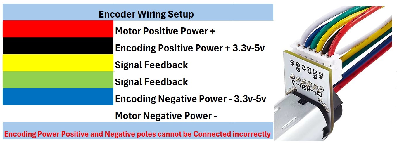
Wiring & Encoder Operation
The motor uses a 6-wire cable that separates motor power from encoder power and signal lines for safe and reliable operation.
- Red (M2): Motor positive power (+)
- White (M1): Motor negative power (–)
- Black (VCC): Encoder positive power (+3.3V–5V)
- Blue (GND): Encoder ground (0V)
- Green (C1): Encoder Channel A signal output
- Yellow (C2): Encoder Channel B signal output
Important: Encoder power polarity must be connected correctly. Reversing VCC and GND may permanently damage the Hall encoder.
Encoder Signal Explanation (C1 & C2)
- The built-in encoder outputs two digital signals, C1 and C2, which are similar in pulse frequency but phase-shifted by 90°. This is known as quadrature encoding.
- Both C1 and C2 generate square-wave pulses as the motor rotates.
- The pulse count is used to calculate motor speed and rotational movement.
- The order in which C1 and C2 change state determines direction:
- If C1 leads C2, the motor is rotating in one direction.
- If C2 leads C1, the motor is rotating in the opposite direction.
- By reading both channels together, a controller can accurately determine speed, direction, and relative position, enabling precise motion control, odometry, and PID speed regulation.
Applications
- Mobile robots & line-following robots
- Encoded wheels and speed feedback systems
- Smart locks & actuators
- DIY electronics and automation projects


