


This is DIY night light kit allows you to use use any infrared remote control, such as your TV remote (not included), to control the kit light switch.
It has a high quality PCB with clearly marked components especially suitable for beginners.
1.Introduction:
RCN-1 is a DC 9V-12V Infrared Remote Control DIY Kit. User can use any infrared remote controller to control the lamp on or off with 18pcs white LED.
2.Feature:
1>.18pcs highlight LED
2>.Perfect simple circuit
3>.Two position brightness control
4>.DIY hand soldering
5>.Infrared Remote Control
3.Parameter:
1>.Product Name:RCN-1 IR Control Lamp DIY Kit
2>.Product Number:RCN-1
3>.Work Voltage:DC 9V-12V
4>.Work Current:30mA
5>.Power Type:5.5mm Power Socket or 9V Battery(Not Included!)
6>.Work Mode:Switch or Infrared Remote Control
7>.Color:White LED
8>.Work Temperature:-40℃~85℃
9>.Work Humidity:5%~85%RH
10>.Size(Installed):65*65*36mm
4.Function:
1>.S1 black button is used to turn ON or OFF lamp.
2>.S2 self-locking switch is used to change led brightness. 12pcs LED turn ON or 18pcs LED turn ON.
3>.Any infrared remote controller to control the lamp on or off.
5.Application:
1>.Training welding skills
2>.Student school
3>.DIY production
4>.Project Design
5>.Electronic competition
6>.Gift giving
7>.Crafts collection
8>.Home decoration
9>.Souvenir collection
10>.Graduation design
11>.Holiday gifts
6.Installation Tips:
1>.User needs to prepare the welding tool at first.
2>.Please be patient until the installation is complete.
3>.The package is DIY kit.It need finish install by user.
4>.The soldering iron can't touch the components for a long time(1.0 second), otherwise it will damage the components.
5>.Pay attention to the positive and negative of the components.
6>.Strictly prohibit short circuit.
7>.User must install the LED according to the specified rules.Otherwise some LED will not light.
8>.Install complex components preferentially.
9>.Make sure all components are in right direction and right place.
10>.Check that all of the LED can be illuminated.
11>.It is strongly recommended to read the installation manual before starting installation!!!
12>.Please wear anti-static gloves or anti-static wristbands when installing electronic components.
7.Installation Steps(Please be patient install!!!):
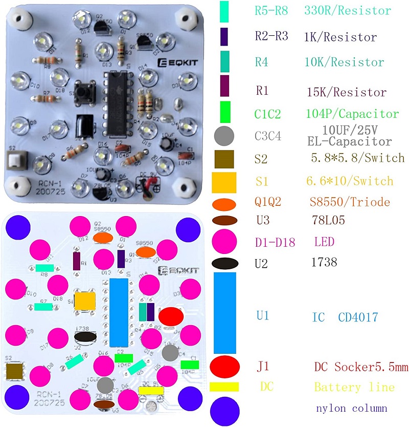
1>.Step 1: Install 4pcs 330ohm Metal Film Resistor at R5-R8.
2>.Step 2: Install 2pcs 1Kohm Metal Film Resistor at R2,R3.
3>.Step 3: Install 1pcs 10Kohm Metal Film Resistor at R4.
4>.Step 4: Install 1pcs 15Kohm Metal Film Resistor at R1.
5>.Step 5: Install 18pcs LED at D1-D18.The longer pin is inserted into the rectangular pad(positive pole). The shorter pins are inserted into the round pads.
6>.Step 6: Install 2pcs 0.1uF 104 Ceramic Capacitor at C1,C2.
7>.Step 7: Install 1pcs TO-92 78L05 Voltage Regulator at U3.
8>.Step 8: Install 2pcs TO-92 S8050 Transistor at Q1,Q2.
9>.Step 9: Install 1pcs DIP-16 CD4017 IC at U1.There is a mark on one end of the IC and there is a mark on PCB where the IC can place on.These two marks are corresponding to each other and are used to specify the installation direction of the IC.
10>.Step 10: Install 2pcs 10uF 25V Electrolytic Capacitor at C3,C4.Pay attention to distinguish between positive and negative.The Longer pin is positive pole.The longer pin is inserted into the rectangular pad.
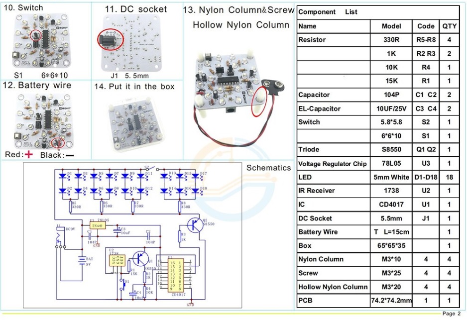
11>.Step 11: Install 1pcs 6*6*10mm Black Button at S1.
12>.Step 12: Install 1pcs TO-92 78L05 Voltage Regulator at U2.
13>.Step 13: Install 1pcs 5.8*5.8mm Self-locking switch at S2.
14>.Step 14: Install 1pcs 5.5mm DC Socket at J1 on another side.
15>.Step 15: Install 4pcs M3*10mm and 4pcs M3*20mm Nylon Column on PCB.
16>.Step 16: Install 1pcs 9V Battery socket at DC 9V. Note: Red wire connect to ‘ + ’ .
17>.Step 17: Install 9V battery(not included) and then place lamp on plastic shell.Then press button to switch lamp.


