


The geeekus 4 channel relay module can be used to activate up to 250V AC and 30V DC from a signal coming from a microntroller source like an arduino, raspberry pi, avr, etc., allowing you to switch up to four devices.
The module has 4 LEDs that indicate the state of the module.There is a red power activation LED that lights when a signal is received on the IN pin. When a signal is received, an audible click can be heard as the relay triggers, connecting the output pins.
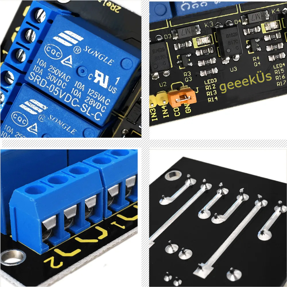
The four relays on the module are rated for 5V, which means the relay is activated when there is approximately 5V across the coil. The contacts on each relay are specified for 250VAC and 30VDC and 10A in each case, as marked on the body of the relays.
On board the unit has a jumper that can provide overall control. For normal operation the jumper is kept in place. This allows any signal on the input pins to trigger the relays. Removing the jumper prevents this from happening. The jumper can then be replaced by a sensor or circuit of some kind that makes the connection under certain conditions. For example, when its bright outside there is no need for lights, so you install a photosensitive resistor.
The pins are meant for standard sockets with a pin pitch of 2.54mm. Each relay has a set of screw terminals with labels to indicate the standard off state relationship between them.
| Pin | Description |
|---|---|
| GND | 0V |
| VCC | 5V |
| IN1 | 0 or 5V/HIGH or LOW |
| IN2 | 0 or 5V/HIGH or LOW |
| IN3 | 0 or 5V/HIGH or LOW |
| IN4 | 0 or 5V/HIGH or LOW |
| COM | Drive LOW to allow standard operation |
| GND | 0V |
Specifications:
- Control signal: TTL voltage
- Active at HIGH level
- Rated load:
10A 250VAC
10A 125VAC
10A 30DC
10A 28VDC
- Rated Through-current: 10A(NO) 5A(NC)
- Max Switching Voltage: 250VAC 30VDC
- Contact actuation time: ﹤10ms
- Definition of module pins:
i) Pin 1- Pin 4----Controlling end

 ii) Power supply (VCC)

 iii) Ground (GND)
Sample Code
int BASE = 2 ;  // I/O pin connected to the first relay
int NUM = 4;   //total number of all relays
void setup()
{
  for (int i = BASE; i < BASE + NUM; i ++)
  {
    pinMode(i, OUTPUT);   //set digital I/O pin as output
  }
}
void loop()
{
  for (int i = BASE; i < BASE + NUM; i ++)
  {
    digitalWrite(i, LOW);    //set digital I/O pin as ‘low’, i.e. turning off the relay gradually
 delay(200);        //delay
  }
  for (int i = BASE; i < BASE + NUM; i ++)
  {
    digitalWrite(i, HIGH);    // set digital I/O pin as ‘low’, i.e. turning on the relay gradually
delay(200);        //delay
  }
}


