
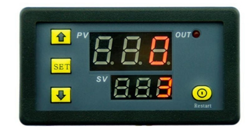

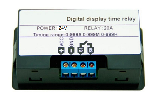
This is a Digital Cycle Timer Delay Relay Board Module operating at 24VDC, current 20A with 0-999 second timing range on a digital LED Display.
Dimensions mm: 72 L x 40 W x26 H
Instructions:
- After setting the data, you must wait 6 seconds, 6s post modules automatically save memory set data.
- Press SET key once to enter the time setting mode, the red LED flashes, press the key to increase or decrease the setting time T1.
- After setting time T1, short press the SET key again, the green LED flashes, and the time is set by pressing the key Time T2, T2 time setting is completed, press SET key again, the system will automatically save the memory setting time or wait for 6s, 6s module will automatically save the data memory.
- Long press SET, enter parameter setting mode. There are two sets of parameters for the user to select P0, P1. Short press SET in the current mode to switch between P0 and P1.
- In P0 parameter can be set by pressing the key to adjust their own timing mode. In the P1 parameter can be set by adding and subtracting keys work mode.
P0--0: T1 Timing mode is in seconds.
P0--1: T1 timing mode is in minutes.
P0--2: T1 Timing Time mode is in hours.
P1--0: Delay T1 time, relay pull (T1 timer)
P1--1: Relay release after T1 time delay (T1 timer)
P1--2: Delay T1 time, relay pull (T1 timer), and then relay release after T2 time delay (T2 timing), then it is finished.
P1--3: Relay release after T1 time delay (T1 timer), then delay T2 time, relay pull (T2 timing), then it is finished.
P1--4: Delay T1 time, relay pull (T1 timer), and then relay release after T2 time delay (T2 timer), cycling.
P1--5: Relay release after T1 time delay (T1 timer), then delay T2 time, relay pull (T2 timer), cycling.


